


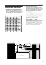

Control panel
7
I
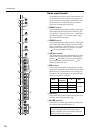
M1–M8
switches
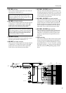
These switch on/off the signal which is sent from the
input channel to MIX buses 1–8.
J
M1–M8
mix level controls
These controls send the signal from the input channel
to MIX buses 1–8. When the control is in the “
▲
”
position, the level is nominal (0 dB). Use the PRE
switch (
P
) to switch between pre/post fader.
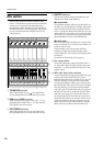
K
M9–M12
switches
These are on/off switches for the signals that are sent
from the input channel to MIX buses 9–12.
L
M9–M12
mix level controls
These controls send the signal from the input channel
to MIX buses 9–12. When the control is in the “
▲
”
position, the level is nominal (0 dB). Use the PRE
switch (
P
) to switch between pre/post fader.
M
M13/M14
,
M15/M16
switches
These are on/off switches for the signals that are sent
from the input channel to MIX buses 13–16. M13 and
14, and M15 and M16 are stereo pairs, and each pair is
turned on/off by one switch. Use the PRE switch (
P
)
to switch between pre/post fader.
N
M13/M14
,
M15/M16
mix level controls
These controls send the signal from the input channel
to MIX buses 13–16. When the control is in the “
▲
”
position, the level is nominal (0 dB). M13 and M14,
and M15 and M16 are stereo pairs, and the output
level of each pair is controlled by one knob. Use the
PRE switch (
P
) to switch between pre/post fader.
O
M13/M14
,
M15/M16
pan controls
These controls set the panning of the signals that are
sent from the input channel to MIX buses 13/14 or
MIX buses 15/16. When the control is in the center
position, an equal amount of signal will be sent to
both buses.
P
PRE
switches
These are pre-fader/post-fader switches for the signals
that are sent from the input channel to MIX buses 1–
16. Pre/post can be switched independently for each
group of MIX buses: 1–4, 5–8, 9–12, and 13–16. When
the switch is pressed ( ), the post-EG/pre-fader sig-
nal will be sent to the corresponding group of MIX
buses.
Note:
If these switches are off, no signal will be sent
to the corresponding MIX bus from this input
channel, regardless of the switch setting of the vari-
able/fixed select section (page 13).
Note:
For MIX bus pairs for which the variable/fix
select section (page 13) switch is set to FIX, the out-
put level which is sent from each input channel to
the bus will be fixed, and therefore the mix level
control setting will have no effect.
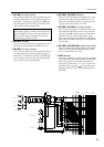
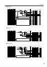
from Ctrl Master
from VCA Master
ON/EDIT
CHECK ON
CONTROL
ST
L R
PFL
L R ON
MIX
(FIX)
MIX
(VARIABLE)
M8
M7
M6
M5
PRE
M4
M3
M2
8
7
2
1
PFL
DIRECT OUT
Internal Jumper
PRE
M15/
M16
M13/
M14
PAN
PAN
M12
M11
M10
M9
PRE
PRE
M1
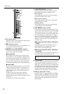
PEAK
NOM
SIGNAL
ST
VCA
INSERT I/O
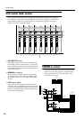
4 Stage EQ
EQHPF
HPF
PHANTOM
MASTER
+48V
Input
1-24/1-40
+48V
26dB
PAD
PAN
HA
GAIN
1 2 3 4 5 6 7 81 3 5 7 9
2 4 6 8
11 13 15
10 12 14 16
f
g
f
g
f
g
Q
f
g
Q
LO
LO-MID
HI-MID
HI