


26
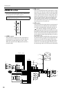
Rear panel
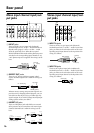
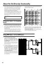
Mono input channel input/out-
put jacks
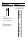
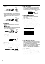
A INPUT jacks
These are XLR-3-31 type input jacks (balanced).
Nominal input level is –16 dB ~ –60 dB when the 26
dB pad switch (page 6) is off, or +10 dB ~ –34 dB
when the pad switch is on. When the rear panel
PHANTOM MASTER switch and the phantom power
switches for the corresponding input channel are on,
+48 V phantom power is supplied. Pin wiring is as fol-
lows.
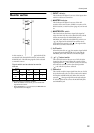
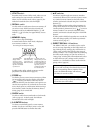
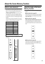
B DIRECT OUT jacks
These are 1/4" phone jack direct outputs (unbal-
anced). Nominal output level is 0 dB. Pin wiring is as
follows.
With the factory settings, the post-fader signal is out-
put. However by changing internal jumpers, you can
switch this so that the pre-EQ or pre-fader/post EQ
signal is output. If you wish to change internal jumper
settings, please contact your dealer.
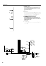
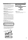
C INSERT I/O jacks
These are TRS phone jacks which allow an external
effect processor to be inserted into each mono input
channel. Nominal level is 0 dB. Pin wiring is as fol-
lows.
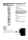
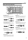
Stereo input channel input/out-
put jacks
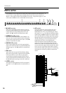
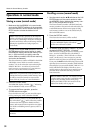
D INPUT A jacks
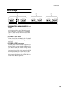
These are XLR-3-31 type input jacks (balanced).
Nominal input level is +10 dB ~ –30 dB. To use these
jacks, you must set the A/B select switch of the corre-
sponding stereo input channel to the A position. Pin
wiring is as follows.
E INPUT B jacks
These are RCA phono input jacks (unbalanced).
Nominal input level is +10 dB ~ –20 dB. To use these
jacks, you must set the A/B select switch of the corre-
sponding stereo input channel to the B position. Pin
wiring is as follows.
4
NPUT
ECT OUT
ERT I/O
3
INPUT
DIRECT OUT
0 dB
INSERT I/O
0 dB
2
INPUT
DIRECT OUT
0 dB
INSERT I/O
0 dB
1
INPUT
DIRECT OUT
0 dB
INSERT I/O
0 dB
INSERT
OUT IN
24
INPUT
DIRECT OUT
0 dB
INSERT I/O
0 dB
23
INPUT
DIRECT OUT
0 dB
INSERT I/O
0 dB
22
INPUT
DIRECT OUT
0 dB
INSERT I/O
0 dB
21
INPU
DIRECT
0 dB
INSERT
0 dB
H
3
T A
T
B
ST CH 2
INPUT A
INPUT B
L
R
R
L
ST CH 1
INPUT A
INPUT B
L
R
R
L
A
B
C
Male XLR plug
1 (ground)
3 (cold)
2 (hot)
1/4" phone plug
Tip (send)
Sleeve (ground)
1/4" phone plug
1/4" phone plug
1/4" TRS phone plug
To processor’s input
From processor’s output
Connect to INSERT I/O jack
Tip (send)
Tip (send)
Ring (return)
Sleeve (ground)
Sleeve (ground)
Tip (return)
Sleeve (ground)
INSERT
OUT IN
ST CH 4
INPUT A
INPUT B
L
R
R
L
ST CH 3
INPUT A
INPUT B
L
R
R
L
ST CH 2
INPUT A
INPUT B
L
R
R
L
ST CH 1
INPUT A
INPUT B
L
R
R
L
4
5
Male XLR plug
1 (ground)
3 (cold)
2 (hot)
Phono plug
Tip
Sleeve