


About the Scene Memory function
35
(control change transmission/reception)
.........................oFF/GrP/on (Factory setting: on)
This specifies whether or not control change messages
will be transmitted and received via MIDI IN/OUT. If
this is set to “ ,” control change messages will not
be transmitted or received. If this is set to “ ,” con-
trol changes 1–104 received from an external device
will switch the corresponding channel on/off. (If mute
groups can be used, control changes 105–112 can also
be used to switch mute groups 1–8 on/off.) Also,
when the ON/EDIT switches of the M3000A are oper-
ated, the corresponding control change will be trans-
mitted. If this is set to “ ,” only control change
numbers (105–112) which correspond to mute groups
will be transmitted.
(program change reception omni on/off)
...............................on/oFF (Factory setting: oFF)
This specifies whether or not the MIDI channel speci-
fied by the CH (MIDI channel) parameter will be
valid. When this setting is “ ,” program changes will
be received on all MIDI channels. When this setting is
“ ,” program changes will be received only on the
MIDI channel specified by the CH (MIDI channel)
parameter.
(echo back) ........on/oFF (Factory setting: oFF)
When this parameter is “ ,” messages received at the
MIDI IN connector will be retransmitted from the
MIDI OUT connector.
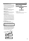
However if a bulk dump request is received, bulk
dump data will be output, and the bulk dump request
message itself will not be retransmitted (echoed).
(bulk out) .....................................ALL/1–128
This operation transmits all scene memories (ALL) or
a specified scene memory (1–128) as MIDI bulk
dump data from the MIDI OUT connector. Select
“ ” or “ ” ~ “ ” and then press the STORE
switch to begin transmission. During transmission,
the display will indicate “ .”
(bulk dump request) .....................ALL/1–128
This operation transmits a request for a bulk dump
from the MIDI OUT connector. If the respective
MIDI IN/OUT connectors of two M3000A units are
connected, such a request will cause all scene memo-
ries (ALL) or the specified scene memory (1–128) of
the other M3000A to overwrite the scene memory (or
memories) of this M3000A. After selecting “ ” or
“ ” ~ “
,” press the STORE switch to transmit the
bulk dump request MIDI message.
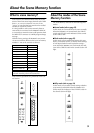
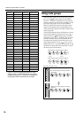
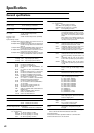
Control change table
The following table shows the M3000A channel/bus
to which each control number is assigned. If the CC
(control change) item is turned ON in utility mode, a
control change message with a value of 64-127 will
turn on the corresponding channel/bus, and a control
change message with a value of 0-63 will turn it off. In
the same way, operating the ON/EDIT switches of the
M3000A will transmit the corresponding control
change message from the MIDI OUT connector.
Also, if mute groups can be used (refer to page 36),
control change numbers 105–112 can be used to
switch mute groups 1–8 on/off.
Control No. ON/EDIT Switch Control No. ON/EDIT Switch
0 30 CH INPUT 30
1 CH INPUT 1 31 CH INPUT 31
2 CH INPUT 2 32 CH INPUT 32
3 CH INPUT 3 33 CH INPUT 33
4 CH INPUT 4 34 CH INPUT 34
5 CH INPUT 5 35 CH INPUT 35
6 CH INPUT 6 36 CH INPUT 36
7 CH INPUT 7 37 CH INPUT 37
8 CH INPUT 8 38 CH INPUT 38
9 CH INPUT 9 39 CH INPUT 39
10 CH INPUT 10 40 CH INPUT 40
11 CH INPUT 11 41 CH INPUT 41
12 CH INPUT 12 42 CH INPUT 42
13 CH INPUT 13 43 CH INPUT 43
14 CH INPUT 14 44 CH INPUT 44
15 CH INPUT 15 45 CH INPUT 45
16 CH INPUT 16 46 CH INPUT 46
17 CH INPUT 17 47 CH INPUT 47
18 CH INPUT 18 48 CH INPUT 48
19 CH INPUT 19 49 ST INPUT 1
20 CH INPUT 20 50 ST INPUT 2
21 CH INPUT 21 51 ST INPUT 3
22 CH INPUT 22 52 ST INPUT 4
23 CH INPUT 23 53 CH INPUT 49
24 CH INPUT 24 54 CH INPUT 50
25 CH INPUT 25 55 CH INPUT 51
26 CH INPUT 26 56 CH INPUT 52
27 CH INPUT 27 57 CH INPUT 53
28 CH INPUT 28 58 CH INPUT 54
29 CH INPUT 29 59 CH INPUT 55