


38
About the VCA functionality
The VCA master section of the M3000A contains eight
VCA master faders. These VCA master faders 1–8 can
be used to control the overall input level of input
channels assigned to the corresponding VCA groups
1–8.
If you wish to use the VCA functionality, set the rear
panel VCA MASTER/SLAVE switch to the MASTER
position.
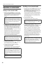
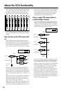
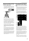
Basic function of the VCA master fad-
ers
The VCA master faders control the gain of the pre-
fader signal of input channels which are assigned to
the corresponding VCA group. The following diagram
shows the flow of audio signals and control signals
(CV) when input channel 1 is assigned to VCA group
1.
• The gain of an input channel which is assigned to a
VCA group can be controlled both by the channel
fader and by the VCA master fader. For example if the
channel fader is set to 0 dB and the VCA master fader
is set to –10 dB, the gain will be 0 dB + (–10 dB) = –10
dB.
• When you operate a VCA master fader, it will affect all
MIX buses (except for MIX buses set to pre-fader),
matrix, and STEREO bus to which a signal is being
sent from the corresponding channel.
• When a VCA master fader is in the 0 dB position (the
NOMINAL indicator of that fader will be lit) it is in
unity gain, and that VCA will produce no boost or cut.
• When the VCA MUTE switch of a VCA master fader is
turned on (the indicator beside the switch will be lit),
no control signal will be sent from that VCA master
fader, and the post-fader signal of input channels
assigned to that VCA group will be muted.
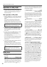
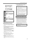
Using a single VCA master fader to
control multiple channels
If two or more channels are assigned to the same VCA
group, you can use a single VCA master fader to con-
trol them. The following diagram shows an example
of the signal flow when VCA GROUP select switch 1 is
turned on for input channels 1, 5, and 16.
• If two or more input channels are assigned to a VCA
group, the gain of each channel can be controlled both
by the channel fader and by the VCA master fader.
• When you operate a VCA master fader, it will affect all
MIX buses (except for MIX buses set to pre-fader),
matrix, and STEREO buses to which the input chan-
nel assigned to that VCA group is being sent.
• When a VCA master fader is in the 0 dB position (the
NOMINAL indicator of that fader will be lit) it is in
unity gain, and that VCA will produce no boost or cut.
• When the VCA MUTE switch of a VCA master fader is
turned on (the indicator beside the switch will be lit),
the post-fader signal of all input channels assigned to
that VCA group will be muted.
S
MIX 13/14MIX 11/12 MIX 15/16
NOMINALNOMINAL
VCA
MUTE
VCA
MUTE
5
0
5
10
20
30
40
50
60
10
5
0
5
10
20
30
40
50
60
10
NOMINAL
VCA
MUTE
5
0
5
10
20
30
40
50
60
10
MIX 9/10
NOMINAL
VCA
MUTE
5
0
5
10
20
30
40
50
60
10
MIX 7/8
NOMINAL
VCA
MUTE
5
0
5
10
20
30
40
50
60
10
MIX 5/6
NOMINAL
VCA
MUTE
5
0
5
10
20
30
40
50
60
10
MIX 3/4
NOMINAL
VCA
MUTE
5
0
5
10
20
30
40
50
60
10
MIX 1/2
NOMINAL
VCA
MUTE
5
0
5
10
20
30
40
50
60
10
INPUT 1
VCA
VCA MASTER
FADER 1
CH 1
VCA GROUP SW 1
CH1
FADER
OUT
OUT
OUT
MIX
MATRIX
STEREO
Audio signals
Control signals
INPUT 1
VCA MASTER
FADER 1
CH 1
VCA GROUP SW 1
INPUT 5
CH 5
VCA GROUP SW 1
INPUT 16
CH 16
VCA GROUP SW 1
CH1
FADER
OUT
OUT
OUT
CH5
FADER
CH16
FADER
VCA
Audio signals
Control signals
VCA
VCA