


42 X32 COMPACT DIGITAL MIXER User Manual
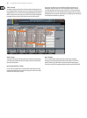
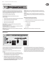
7.2 .3 Home Screen: Gate Tab
The gate tab displays all aspects of the channel noise gate and allows for very
deep control of the gate eect. Whereas the top panel’s dedicated gate section
allows control of the gate’s threshold and in/out status, the gate tab oers many
more controls. This tab can also be accessed directly by pressing the “View”
button in the top panel Gate section.
The gate tab contains the following parameters, divided among two pages,
thatcan be adjusted using the six rotary-push encoders:
Page 1
1. Adjust the 1st encoder to set the input threshold of the gate.
2. Tap the 1st encoder to toggle the noise gate in/out of the signal path.
3. Adjust the 2nd encoder to set the range of a “ducking” eect applied to
thechannel.
4. Tap the 2nd encoder to toggle the ducker eect in/out of the signal path.
5. Adjust the 3rd encoder to set the attack time of the onset of the noise
gateeect.
6. Adjust the 4th encoder to set the hold time of the noise gate eect.
7. Adjust the 5th encoder to set the release time of the noise gate,
controllinghow quickly the gate opens up and lets the signal through.
Page 2
1. Encoders 1 and 2 function the same on pages 1 and 2.
2. Adjust the 4th encoder to set the frequency of the key lter that can be used
to trigger the noise gate.
3. Tap the 4th encoder to toggle the key lter on/o, allowing a specic
frequency to control the gate.
4. Adjust the 5th encoder to set the steepness of the EQ slope used in the
keylter.
5. Tap the 5th encoder to send the key source to the solo bus, allowing the key
source to be monitored and evaluated.
6. Adjust the 6th encoder to select the specic key source to be used.
Choicesinclude “self” (the channel’s own signal) as well as any other
input/output of the console.
7. Tap the 6th encoder to assign the selected key source to the gate.
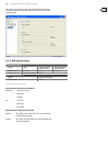
7.2 .4 Home Screen: Dynamics Tab
The dynamics tab displays all aspects of the channel compressor and allows for
very deep control of the eect. Whereas the top panel’s dedicated compressor
section allows control of the threshold and in/out status, the compressor tab
oers many more controls. This tab can also be accessed directly by pressing the
“View” button in the top panel Dynamics section.
The dynamics tab contains the following parameters that can be adjusted using
the six rotary-push encoders:
Page 1
1. Adjust the 1st encoder to set the input threshold of the compressor.
2. Tap the 1st encoder to toggle the compressor in/out of the signal path.
3. Adjust the 2nd encoder to set the ratio of the compressor.
4. Tap the 2nd encoder to switch the channel dynamics eect between
compression and expansion.
5. Adjust the 3rd encoder to set the attack time of the compressor eect.
6. Tap the 3rd encoder to switch the compressor between Peak and RMS
(root-mean-squared) mode, where the average level of the signal is
evaluated more than any specic peak of the channel material.
• PEAK: A peak sensing compressor responds to the instantaneous level
of the input signal. While providing tighter peak control, peaksensing
might yield very quick changes in gain reduction, more evident
compression, or sometimes even distortion. This mode is very suitable
for control/limiting of dynamic material.
• RMS: In this mode, the compressor applies an averaging function on the
input signal before its level is compared to the threshold. Thisallows
a more relaxed compression that also more closely relates to our
perception of loudness. Sharp dynamic transients will be less aected in
this mode. This mode is good for controlling levels in a mix.
7. Adjust the 4th encoder to adjust the “hold” time of the compressor.
• “Hold” time is a parameter not often found on commercial units, but is
very handy. If a compressor is set to use a very fast attack/release time,
audible distortion can occur, because the compressor is trying to work
on individual waveform cycles of the signal instead of sound envelope
as a whole. The “hold” parameter works around this issue by providing
a short delay. This delay prevents the compressor from releasing until a
certain time has passed.
8. Tap the 4th encoder to switch between Linear and Logarithmic modes for the
compressor. Following are some brief denitions of these dierent modes:
• LOG: This mode is used in many well-respected compressors and is the
natural result of more recent analogue units employing logarithmic
side chains and resistor/capacitor time constants. The exponential/
dB law has some interesting characteristics. Firstly, the time taken to
complete a compression event tends to stay the same however large
the dynamic signal excursion is. Also, since the peak rate of gain change
increases with dynamic excursion, the resulting harmonic content due
to compression tends to follow the loudness of the program in a way
the ear expects. This helps to mask the eects of the compression and
thus provides the most forgiving solution, being tolerant to diering
timing settings and program material. This makes it the best choice
for general compression use and overall dynamic control of complex
musical program.