


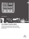

6 X32 COMPACT DIGITAL MIXER User Manual
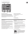
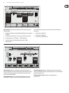
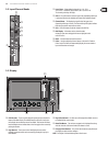
Input Channel Banks
You will nd a select button on top of every channel that is used to direct the
control focus of the user interface, including all channel related parameters
(channel strip and main display), tothat channel. Please note that at any time,
there is exactly onechannel selected (either Input Ch 1-32, Aux1-8, FXReturns
1L-4R, Mix Bus 1-16, Main LR/C, orMatrix 1-6). DCA Groups (digitally controlled
amplier) cannot be selected because they control a number of assigned
channels rather than one specic channel.
The Input Channels section of the console is locatedon the left hand side,
and oers 16 separate input channel strips. These 16 channel strips represent
three separate layers of inputs for the console, including:
• Input Channels 1-8
• Input Channels 9-16
• Input Channels 17-24
• Input Channels 25-32
• Aux Inputs 1-6/USB playback
• FX Returns
Press any of the correspondingly labeled layer buttons on the left side of the
console to switch the input channel bank to any of the six layers listed above.
The button will illuminate, reminding you which layer is active.
Two more layers (Bus Master 1-8 and 9-16) are also oered, allowing you to
adjust the levels of the 16 Mix Bus Masters, which is useful when you wish to
include Bus Masters into DCA Group assignments.
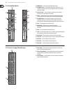
On each fader strip you will nd a motorized 100mm level fader, Mute and
Solo buttons, aGate indicator, an input level meter, Compressorindicator,
and the channel selectbutton.
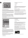
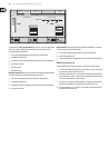
Each of the 8 input channels has an individual (andcustomizable) color LCD
screen that can display a channel number, nickname, and even a graphical
channel icon. In the event that a channel’s input source has been changed to an
input signal that diers from the default setup, the LCD displaywill also indicate
the name of the actual input source.
Ch01
Aux5
Soundcard
PC
Example: Channel 01 has the nickname Soundcard and is fed from Aux input 5.
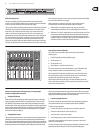
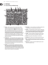
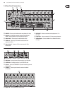
Channel Strip and Monitoring
The X32 COMPACT’s channel strip oers dedicated controls for the most important
processing parameters of the currently selected channel. To adjust controls for a given
channel strip, simply press the Select button on the desired input or outputchannel.
Certain sections of the channel strip (such as the low cut lter, noise gate, EQ and
compressor) contain a respectively labeled button that can be pressed to switch
the specic eect on and o. Thebutton illuminates to show the eect is active,
and goes dark when bypassed.
Within the channel strip, the rotary control knobs are surrounded by an amber
LED collar that indicates the parameter’s value. Whenever this backlit knob is
turned o, it indicates that this specic control/parameter is not available for
the selected channel type. For example, if an output bus is currently selected,
theLED collar and the gainknob are turned o, because there is no input gain to
be controlled on an output bus.
The channel strip consists of the following sub-sections:
• Cong/Preamp
• Gate, Dynamics
• Equalizer
• Main Bus
Each of these subsections correspond to the processing steps of the currently
selected channel, and they each have their own View button that, when pressed,
switches the Main Display to a page displaying all related parameters for
thatsubsection.
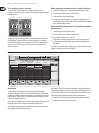
Monitoring and Talkback
There are two separate Level controls in this section, one for the headphone
outputs located on either side of the console, and a second one for the monitor
outputs located on the rear panel.
Press the section’s View button to edit various monitoring preferences, such as
the input source for the phones bus and the monitor outputs.
This section also contains independent Talkback buttons (A and B). Press the View
button next to the Phones Level knob, then press Page Select right to access the
Talkback A and B edit pages. These screens also contain settings for the optional
goose-neck lamp and the console’s internal test-tone generator.