


49 X32 COMPACT DIGITAL MIXER User Manual
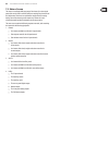
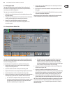
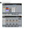
7.4.4 Routing Screen: P16 Tab
The routing screen’s P16 tab allows the user to route various console signal paths
to the rear panel P16 Ultranet output. The Ultranet output allows for 16 channels
of audio to be sent, in digital form, to various accessories such as a personal
monitoring distribution box.
Using the P16 routing screen, the user can congure the P16 output to carry not
only the main LR mix, but also various audio “stems” of program material sources
from a bus send mix, such as a stereo drum mix, stereo keyboards, guitars,
bass, vocals, etc. Musicians on stage would then be free to each craft their own
personal mix of these musical stems, all delivered from the FOH position to stage
over a single Ethernet cable.
To select which audio signals are sent to the P16 bus, perform the followingsteps:
1. Adjust the 1st encoder to select which of the 16 channels in the P16 bus you
wish to select an audio source for.
2. Adjust the 3rd encoder to select a category of audio source to send to the
currently selected P16 channel. These categories include:
• Insert
• Main (LRC)
• Mix Bus
• Matrix
• Direct Out
• Monitor
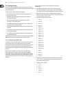
3. Adjust the 4th encoder to select which specic signal path to feed to the
currently selected P16 output. Choices include:
• O
• Main L
• Main R
• Main C/M
• Any of the 16 Mix Outputs
• Any of the 6 matrix outputs
• Any of the 32 direct outputs
• Any of the 8 Auxiliary Outputs
• Any of the FX Direct Outputs
• Monitor L
• Monitor R
• Talkback
4. Tap the 4th encoder to assign the selected output path,
completing the process.
5. Adjust the 5th encoder to select the signal tap point for the output assignment.
This determines where in the audio signal path the source is “tapped” as it is
sent to the P16 output. The available signal tap pointsinclude:
• Input
• Pre-EQ
• Pre-Fader
• Post-Fader
6. Tap the 5th encoder to complete the signal tap point assignment.
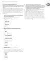
7.4.5 Routing Screen: Card Output Tab:
The routing screen’s card tab allows the user to patch various signal paths to the
physical inputs and outputs of the X-USB card. The X-USB’s signal path provides
32channels of inputs and 32 channels of outputs. The 32 card inputs can be used
as alternate sources for the two input fader layers, switchable in banks of 8.
To assign an output path to the option card, perform the following steps:
1. Adjust the 1st encoder to select which 8-channel output path to send to the
rst 8 outputs of the card. Choices include:
• Local 1-8
• Local 9-16
• Local 17-24
• Local 25-32
• AES50-A 1-8
• AES50-A 9-16
• AES50-A 17-24
• AES50-A 25-32
• AES50-A 33-40
• AES50-A 41-48
• AES50-B 1-8
• AES50-B 9-16
• AES50-B 17-24
• AES50-B 25-32
• AES50-B 33-40
• AES50-B 41-48
• Card 1-8
• Card 9-16
• Card 17-24
• Card 25-32
• Out 1-8
• Out 9-16
• P16 1-8
• P16 9-16
• Aux 1-6/Mon
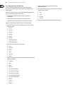
2. Tap the 1st encoder to assign the selected output path,
completing the process.
3. Repeat the process with encoders 2-4 to select output paths for the other
24channels of card outputs.