


Installation ~ Installation
10
Technical Services Group ~ 1-800-283-5936 (USA) ~ 1-801-974-3760
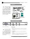
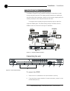
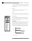
To create a G-Link network
1. Insert a G-Link terminator (provided) in the G-Link In connector of the first
unit in the network.
2. Connect the RJ-45 jumper cable (or Cat. 5 twisted-pair cable) to the G-Link
Out connector of the first unit and to the G-Link In connector of the second
unit. Continue connecting units in the same fashion.
3. Plug the G-Link terminator in the G-Link Out connector on the last unit to
complete the network connections.
Device IDs
Once your physical G-Link network is established (and if you have more than one AP
unit at a site), you need to specify unique device ID numbers for each AP800 on the
network. As shipped from the factory, all AP800 units default as device ID “0”. Set
device ID numbers for each unit at your site by manipulating the front-panel LCD.
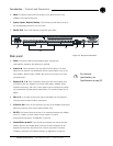
To set the device ID
1. Press the System button, then scroll to Device ID.
2. Press Enter, then scroll through the eight (0–7) options.
3. Press Enter to select the appropriate device ID.
Repeat this process for each
AP product on the G-Link network.
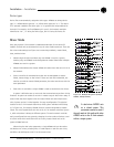
If the same Device ID is assigned to more than one unit of the same type on
the G-Link network, Meter LED “+12” will flash red and Meter LED “0”, “-4”,
“-30”, and Mic 4 will flash green on the affected units. To correct the problem,
change the device ID on one of the units.
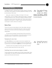
AP800 unit 0
AP800 unit 2
G-Link
Terminator
G-Link
Terminator
AP800 unit 1
Figure 2.4. G-Link Network Connection