


Installation ~ LCD Programming
26
Technical Services Group ~ 1-800-283-5936 (USA) ~ 1-801-974-3760
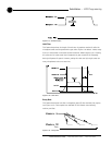
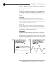
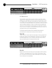
Figure 2.19. Echo Cancellation Setup Default Matrix
EC Reference bus
This bus provides a system-wide echo canceller reference signal. When multiple
AP800 units are linked together and will be using only one output channel to drive
the loudspeaker system, that output must be defined as the sample reference which
will be used by all of the linked AP800s for echo cancellation. It allows the reference
signal to be passed to additional G-Linked mic channels and their associated echo
cancellers. For echo cancellation to function properly, the output which the master
unit will use as the EC reference must be identified to the slave units via the G-Link
(see Figures 2.36 & 2.37 for routing configuration).
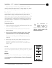
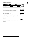
The following example illustrates the echo cancellation setup necessary to
communicate the EC reference from the master unit to the slave unit:
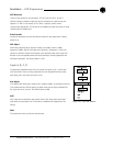
Master Unit
“Define EC Ref #1” tells the master unit which output (in this case, output D) will
be used as the reference for echo cancellation for the master unit. This output (D)
must also be defined as the “G-Link EC Ref bus” which slave units will refer to
when you are defining their EC references (see Figure 2.20).
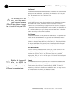
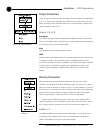
Slave Unit
Because the slave unit will not be using one of its own outputs as the EC reference,
“EC Ref #1” must be defined as the “G-Link EC Ref” only (as shown in Figure
2.21). The slave unit will then use the master’s defined output (in this case, output
D) as its reference for echo cancellation.
Figure 2.20. EC Setup for Multiple Units to One Output (Master Unit)