


5
Introduction ~ Controls and Connections
Technical Services Group ~ 1-800-283-5936 (USA) ~ 1-801-974-3760
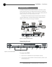
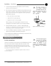
D. Meter. The Meter button takes you directly to the Meter branch of the
AP800’s LCD programming tree.
E. System, Inputs, Outputs, Routing. These buttons provide direct access to
the corresponding sections in the LCD menu.
F. Mic On LED. These LEDs indicate microphone gate status.
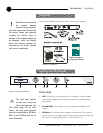
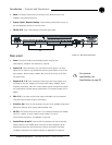
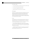
Rear panel
A. Power. This power module accommodates power ranging from
100–240VAC, 50/60Hz. No switching is required.
B. Inputs A–D. These connectors are used with line-level inputs. Line level
inputs can be mixed in any combination with the gated inputs to any of the
eight outputs. Nominal input is 0dBu. Mix level can be easily set for each
non-gated input.
C. Outputs A–D, 1–8. These connectors allows eight line-level outputs to be
connected to the unit. Outputs can include video codecs, AP800s, AP10
Telephone Interfaces, and VCRs. These outputs can be configured to contain
any combination of gated and non-gated inputs. The nominal output level is
0dBm.
D. Mics 1–8. Up to eight mic/line-level inputs (selectable) can be connected
using the three-terminal Phoenix connector(s).
E. G-Link In, Out. These RJ-45 connectors are part of the AP800’s high-speed
digital bus network, which passes audio between units.
F. RS-232. This female DB-9 serial port is for connection between the AP800
and a PC, modem, or other custom remote control. For serial
communications protocol, see Appendix F, page 39.
G.
Control/Status A and B.
These two DB-25 connectors are used to interface
parallel control to the AP800. Most of the pins on these connectors can be
programmed to perform any function via a closure to ground. For pinouts,
including a description of the default settings, see Appendix D on page 36.
AB
C
D E F G
Figure 1.3. Rear panel connections
For electrical
specifications, see
Specifications on page 33.
✍