System 5-B Digital Audio Mixing System Operation Manual GPI/O Event System
151
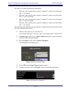
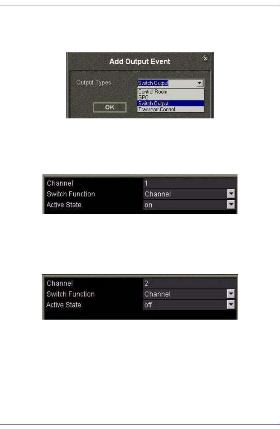
6. From the Output section, click <click to add output event>.
The Add Output Event dialog opens.
Figure 11-6 Add Output Event dialog
7. Select Switch Output from the Output Type dropdown menu.
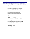
8. Configure the lower area of the Output section to the following settings:
Figure 11-7 Output Event Properties
This turns channel 1 on when camera 1 is selected by the video switcher.
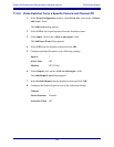
9. Repeat Steps 6–7 to create additional output events to mute channels 2–4 but
use the following settings instead of those depicted in Step 8:
Figure 11-8 Output Event Properties
Figure 11-8 shows Channel 2’s settings; each channel uses its own number but
Switch Function = Channel and Active State = off for each.
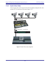
So far, you have achieved the following functionality: when the video switcher selects
camera 1, System 5-B’s channel 1 turns on and channels 2–4 mute. Repeat the steps
above to program channel 2 to turn on when the video switcher selects camera 2 and
mute channels 1, 3, and 4. Each tally input requires a discrete connection at the GP 132.


