


INSTALLATION AND OPERATION
SX TRANSISTOR CONTROL Page 3
January 2000
4.2.5 RF Interference.......................................................................................................................... 17
4.2.6 Suppression............................................................................................................................... 17
4.3 Recommended Lubrication of Pins and Sockets Prior to Installation........................................ 18
4.4 General Troubleshooting Instructions ........................................................................................... 19
4.5 Traction Controller Status Codes ................................................................................................... 20-40
4.6 TMM Status Codes........................................................................................................................... 41-45
4.7 Pump Control Status Codes............................................................................................................. 46-52
Section 5.0 TRUCK MANAGEMENT MODULE (TMM)............................................................................................................53
5.1 General Features .............................................................................................................................. 53
5.2 Operation ...................................................... .................................................................................... 53
5.3 Installation......................................................................................................................................... 53
5.4 Connection Diagrams....................................................................................................................... 53
5.4.1 TMM7A Card Connections ...................................................................................................... 53
5.4.2 TMM7A Typical Brush Wear Sensor Connections ............ ................................................. 53
5.4.3 TMM Pump Control Connections ........................................................................................... 54
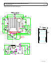
5.5 TMM7A Outline Drawings............................................................................................................... 54
Section 6.0 SX FAMILY - GE HANDSET INSTRUCTIONS ......................................................................................................55
6.1 General Features .............................................................................................................................. 55
6.2 Purpose/Setup Functions ............................................................................................................... 55
6.3 Setup Function Procedures ............................................................................................................ 56
6.3.1 Setup Mode ............................................ .................................................................................. 56
6.3.2 Status Code Scrolling............................................................................................................... 56
6.3.3 SX Handset Plug Connections & Outline Drawing.... ........................................................... 56
6.4 Setup Functions for Traction Controller .. ..................................................................................... 57-62
6.5 Summary of Current Limit Adjustments ......................................................................................... 62
6.6 Setup Functions for Hydraulic Pump Controller . ......................................................................... 64-66
Section 7.0 DASH DISPLAYS.......................................................................................................................................................67
7.1 Application ............................................. ............................................................................................. 67
7.2 Standard Dash Displays .................................. .................................................................................. 67
7.3 Interactive Dash Displays................................................................................................................... 67
7.4 Start-up Display Sequence ................................................................................................................ 68
7.5 Outline Drawings ........................................ ........................................................................................ 68
Section 8.0 TURN ANGLE POTENTIOMETER INSTALLATION..............................................................................................69
8.1 General................................................................................................................................................. 69
8.2 320 Degree Potentiometer Input........................................................................................................ 70
8.3 Turn Angle Input Volts vs. Steer Wheel Degrees vs. Handset Readings..................................... 71
Section 9.0 MEMORY MAPS........................................................................................................................................................72
9.1 Typical Memory Map for Traction Control.................................................................................... 72-74
Table of Contents ( Continued )