


ADJUSTABLE FEATURES
SX TRANSISTOR CONTROLS Page 57
January 2000
ESC
ESCESC
ESC
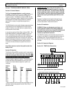
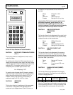
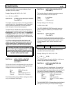
LX
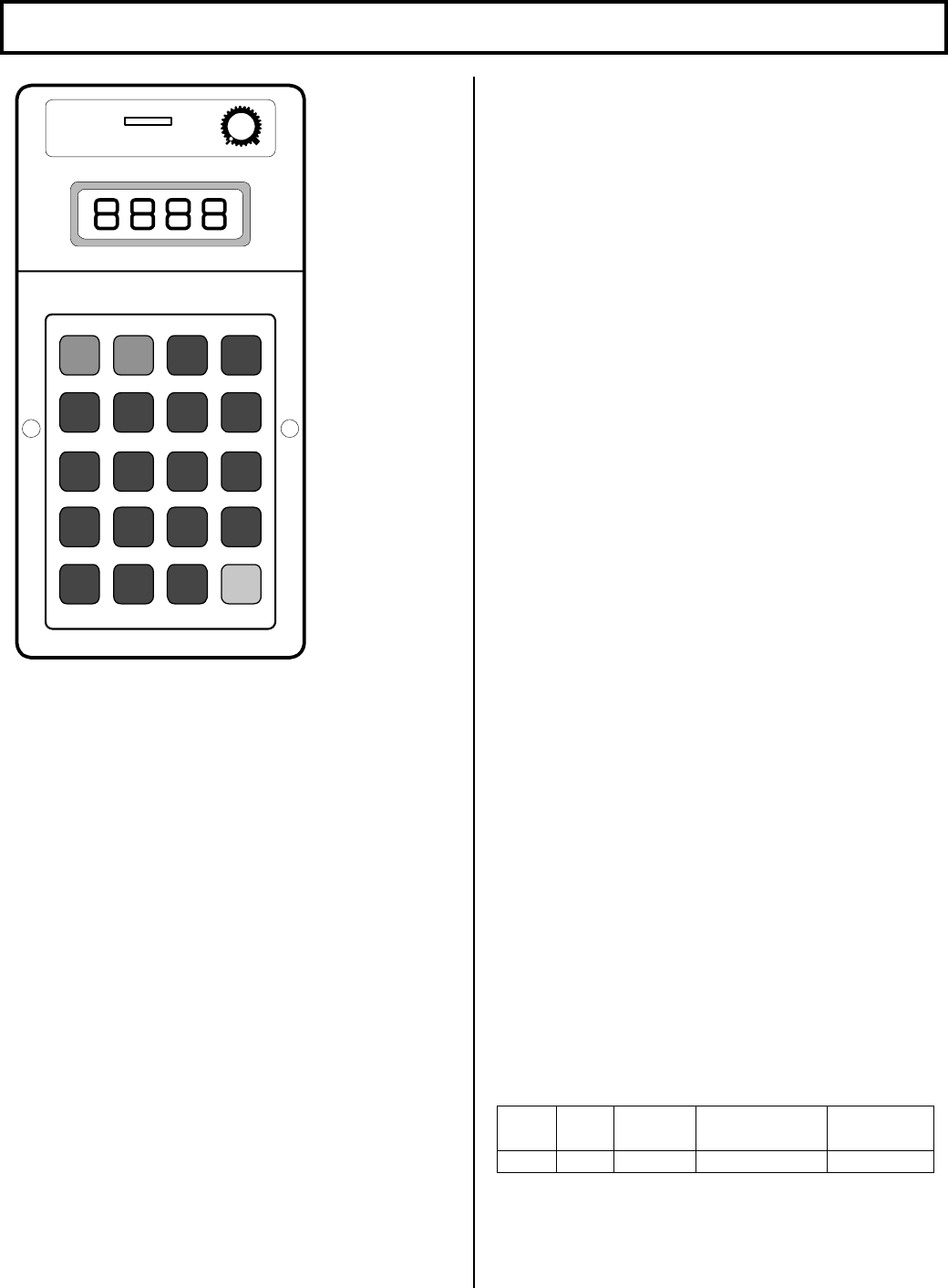
HANDSET
g
EVC
CONT
CONTCONT
CONT
STORE
STORESTORE
STORE
1
5
+ +
9
13
2
6
10
14
3
7
11
15
4
8
12
Section 6.4 Setup Functions for Traction Controller
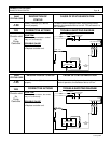
FUNCTION 1 MOTOR VOLTS TO ENABLE AUTO REGEN
(Push 1)
This function allows for the adjustment of motor volts to
enable AutoRegen.
For a setting value of less than 25 (corresponding to a soft
release of auto regen and normal regen), the motor voltage
to enable regen is calculated by multiplying the value of the
setting by 0.375. For example, a setting of 16 will be
multiplied by 0.375 to enable regen at 6 motor volts.
Vm = VAL(setting) X .375
For a setting value of greater than 25, the motor voltage to
enable auto regen is calculated by subtracting 25 from the
setting value and multiplying that number by 0.375. For
example, a setting of 33, the motor volts necessary to
enable auto regen is (33 - 25) x 0.375, or 3 volts.
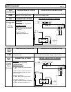
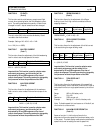
FUNCTION 2 CREEP SPEED
(Push 2)
This function allows for the adjustment of the creep speed
of the vehicle. Creep speed can be adjusted when an
accelerator input voltage between 3.9 and 3.3 volts or an
accelerator ohm input between 6.0K and 4.0K ohms is
provided.
Range 2% to 15% on-time
Set 0 to 255
Resolution 0.05% per set unit
Example Setting of 20 = 3% on-time
Important Note: This function is used to optimize motor
and control performance, and this setting will be
determined by GE and OEM engineers at the time of
vehicle development. This setting must not be changed by
field personnel without the permission of the OEM.
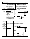
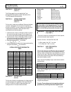
FUNCTION 3 ARMATURE CONTROLLED
ACCELERATION
(Push 3)
This function allows for the adjustment of the rate of time it
takes for the control to accelerate to 100% applied battery
voltage to the motor on hard acceleration.
Range 0.025 to 6.3 seconds
Set 0 to 255
Resolution 0.025 seconds per set unit
Example: Setting of 20 = 0.5 seconds
FUNCTION 4 ARMATURE CURRENT LIMIT
(Push 4)
This function allows for the adjustment of the armature
current limit of the control. The rating of the control will
determine the range of adjustment for this function. Please
refer to the specification sheets and current limit curves for
the control used in your vehicle.
Range See control C/L curves
Set 0 to 255
Example: 0 = min. current, 255 = max.
current
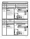
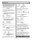
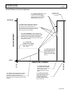
FUNCTION 5 PLUGGING DISTANCE (CURRENT)
(Push 5)
This function allows for the adjustment of the plugging
distance of the vehicle. The larger the current setting, the
shorter the stopping distance.
Min Max Set Resolution
Per Unit Value
Example
If Set at 20
55 455 0 to 255 1.57 amps 86.4 amps
Warning: Plug settings must be made in accordance with
control operating instructions. Too high of a setting could
cause damage to the control system or traction motor.