


ADJUSTABLE FEATURES
TRANSISTOR PUMP CONTROLS Page 64
January 2000
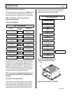
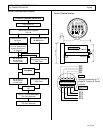
Section 6.6 Setup Functions for Hydraulic Pump Control
FUNCTION 1: NOT APPLICABLE
This function is not applicable to this type of control and
should not be adjusted.
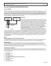
FUNCTION 2: INTERNAL RESISTANCE
COMPENSATION START
(Push 2)
This function allows for the adjustment of the current level
at which the internal resistance compensation feature
(Function 16) will take effect.
Range 0 to 1325 amps
Setting 52 to 255
Resolution 6.5 amps per set unit
Example: Setting of 72 = (72-52) x 6.5 = 130 amps
FUNCTION 3: CONTROLLED ACCELERATION
(Push 3)
This function allows for the adjustment of the rate of time it
takes for the control to accelerate to 96% applied battery
voltage to the motor on hard acceleration.
Range 0.1 to 5.5 seconds
Setting 0 to 255
Resolution 0.021 seconds per set unit
Example: Setting of 20 = 0.52 seconds C/A
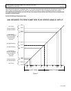
FUNCTION 4: CURRENT LIMIT
(Push 4)
This function allows for the adjustment of the current limit
of the control. The rating of the control will determine the
range of adjustment for this function. Please refer to the
OEM operating instructions for the control used in your
vehicle.
Range See OEM control C/L curves
Setting 0 to 255
Example: 0 = min. current, 255 = max. current
FUNCTION 7: INTERNAL RESISTANCE
COMPENSATION RATE
(Push 7)
This function allows for the adjustment of the rate of time it
takes for the control to add the internal resistance
compensation voltage that is applied to the motor. This
function will add 0.375 volts to the motor at the rate of time
adjusted until the total IR compensation voltage has been
added.
Range 0.0015 to 0.383 seconds
Setting 0 to 255
Resolution 0.0015 seconds per set unit
Example: Setting of 20 = 0.032 seconds
For example, if you had selected 2.08 volts from Function 16
to be added to the motor, it would take 0.18 seconds to add
a total of 2.08 volts. (2.08/0.375)=0.032
FUNCTION 11: SPEED LIMIT 1 (SL1)
(Push 11)
This function allows for the adjustment of the speed limit
(maximum battery volts to the motor) when the SL1 limit
switch input signal is received by the control card. SL1
limit switch is a normally open switch connected to battery
negative, the switch closing enables speed limit.
Range 0% to 100% battery volts
Setting 0 to 255
Resolution 0.375 volts per set unit
Example: Setting of 50=18.75 volts
FUNCTION 12: SPEED LIMIT 2 (SL2)
(Push 12)
Same as Function 11 except using SL2 limit switch for input.
FUNCTION 13: SPEED LIMIT 3 (SL3)
(Push 13)
Same as Function 11 except using SL3 limit switch for input.
FUNCTION 14: NOT APPLICABLE
This function is not applicable to this type of control and
should not be adjusted.
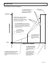
FUNCTION 16: SPEED / TORQUE COMPENSATION
(Push CONT 1)
This function is used to stabilize pump speed at heavy
loads. The voltage selected will be added to the motor at
each 100 amp increment starting at the value set in
Function 2. The voltage compensation selected will be
added in increments of 0.375 volts until the entire voltage is
added. For example, a setting of 2 will be added in 30 steps
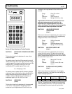
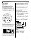
Note: The following functions have function numbers
larger than the numbers on the Handset keyboard. To
access these functions, push the CONT key and the
number shown in the following instructions at the same
time. THE KEY SWITCH MUST BE OPEN.