7
Configuring FCFS Channels in Input Mode
Input mode locks a specified FCFS channel to a
specific input. Table 1 lists the input video formats
you can convert to the specified switcher video
format.
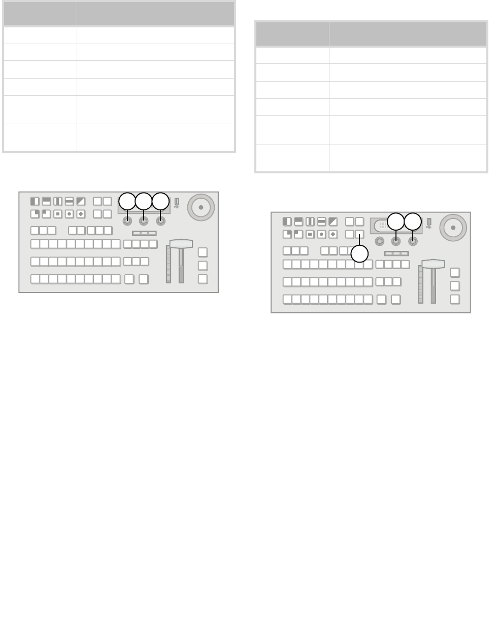
To configure an FCFS channel set to Input mode:
1. Assign an FCFS channel to a specific input.
2. Use the Input knob to select which input the
FCFS channel is assigned to.
3. Use the Frming knob to set the aspect ratio
conversion mode. You can choose from the
following:
• Full — The video signal is scaled
disproportionately to fill the display of the new
aspect ratio. Aspect distortion occurs as the
image is stretched/compressed to fit in the
new aspect ratio.
• Zoom — The central portion of the video
signal is zoomed to fill the display of the new
video format. No aspect distortion is
introduced.
• LttrBx — Black bars are added to the top and
bottom of a 16:9 image to display correctly in a
4:3 video format.
• PllrBx — Black bars are added to the right
and left of a 4:3 image to display correctly in a
16:9 video format.
4. Press the Fcfs1-4 knob to save the changes.
5. Press the Confrm knob to commit the change
and exit the FCFS menu. Press the Cancel knob
to return to the FCFS menu for further editing.
For More Information on...
• Assigning an FCFS channel, refer to the procedure
“To assign an FCFS channel:” on page 6
Configuring FCFS Channels in Bus Mode
Bus mode locks a specified FCFS channel to a
specific bus-pair.
To configure an FCFS channel set to Bus mode:
1. Assign an FCFS channel to a specific bus.
2. Use the Bus knob to select which bus the format
converter / frame synchronizer is assigned to.
3. Use the 2ndCh knob to select the FCFS channel
to assign to the paired bus.
4. Press NEXT.
5. Use the Frming knob to set the aspect ratio
conversion mode. You can choose from the
following:
• Full — The video signal is scaled
disproportionately to fill the display of the new
aspect ratio. Aspect distortion occurs as the
image is stretched/compressed to fit in the
new aspect ratio.
• Zoom — The central portion of the video
signal is zoomed to fill the display of the new
Table 1 Format Conversions for Input Mode
Switcher Video
Format
Allowable Input Formats
1080i / 59.94Hz 480i, 720p / 59.94Hz
1080i / 50Hz 576i, 720p / 50Hz
720p / 59.94Hz –
720p / 50Hz –
480i / 59.94Hz 480i (aspect ratio conversion), 720p,
1080i / 59.94Hz
576i / 50Hz 576i (aspect ratio conversion), 720p,
1080i / 50Hz
Table 2 Format Conversions for Bus Mode
Switcher Video
Format
Allowable Input Formats
1080i / 59.94Hz 480i, 720p / 59.94Hz
1080i / 50Hz 576i, 720p / 50Hz
720p / 59.94Hz –
720p / 50Hz –
480i / 59.94Hz 480i (aspect ratio conversion), 720p,
1080i / 59.94Hz
576i / 50Hz 576i (aspect ratio conversion), 720p,
1080i / 50Hz
2
3
4
