


35
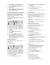
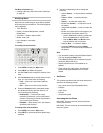
General Purpose Interface (GPI)
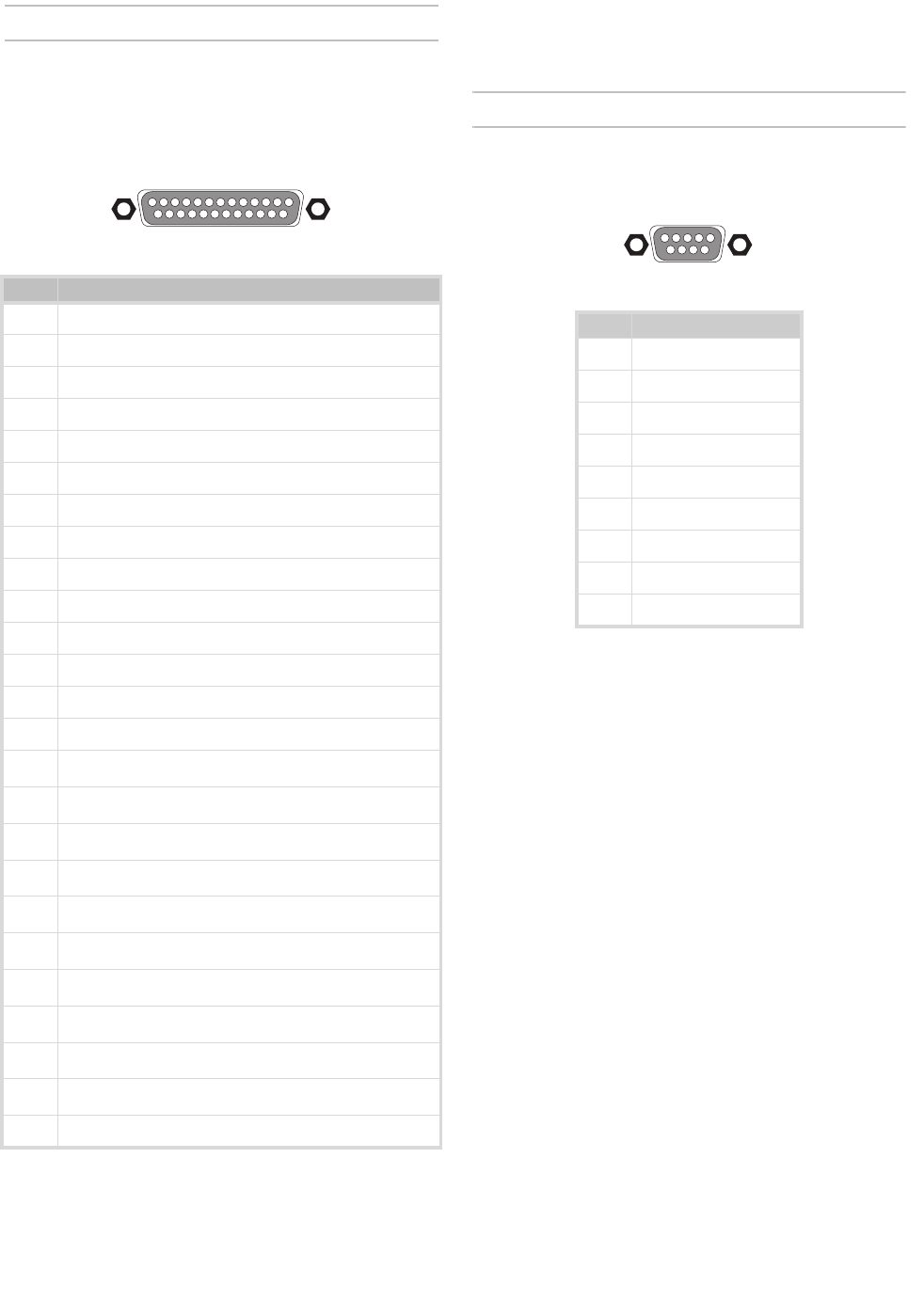
The switcher has 24 GPI inputs that are used to
trigger memory recalls, transitions, and Aux bus input
changes.
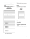
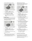
The GPI inputs are assigned as follows (Pin 1 is the
top right pin when looking at the GPI Port).
Figure 12 GPI Port
For More Information on...
• port locations, refer to the section “Control Panel
Rear Connections Overview” on page 2
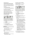
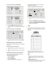
Editor Port
The switcher has an Editor port that allows you to
control your switcher from a device that supports the
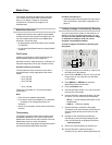
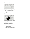
GVG100 editor protocol. The pinout is as follows:
Figure 13 Editor Port
Supported Editors
The following editors have been tested::
• Editware LE-2000 Series
• Sony BVE-900/910
• Sony BVE-2000
For More Information on...
• GVG100 protocol support, refer to the section
“GVG100 Protocol Supported Commands” on
page 44.
• port locations, refer to the section “Control Panel
Rear Connections Overview” on page 2
Pin Trigger
1 Dissolve Key 1
2 Dissolve Key 2
3 Dissolve Key 3 (KM-H 3000 only)
4 Perform Auto Transition
5 Perform Program / Preset Bus cut
6 Perform Key 1 cut
7 Perform Key 2 cut
8 Perform Key 3 cut (KM-H 3000 only)
9 Perform Fade-to-Black
10 Set Aux Bus 1 to Input 1
11 Set Aux Bus 1 to Input 2
12 Set Aux Bus 1 to Input 3
13 Set Aux Bus 1 to Input 4
14 Set Aux Bus 1 to Input 5
15
Recall Memory 0
a
a. Only memory registers from memory bank 0
can be recalled with a GPI trigger.
16
Recall Memory 1
a
17
Recall Memory 2
a
18
Recall Memory 3
a
19
Recall Memory 4
a
20
Recall Memory 5
a
21
Recall Memory 6
a
22
Recall Memory 7
a
23
Recall Memory 8
a
24
Recall Memory 9
a
25 Ground
13 12 11 10 9 8 7 6 5 4 3 2 1
1415
16171819202122232425
Pin Input
1 Not Connected
2Tx-
3Rx+
4 Ground
5 Ground
6 Not Connected
7Tx+
8
Rx-
9
Not Connected
54321
9876