12 - 46
MELSEC-Q
12 CONTROL SUB FUNCTIONS
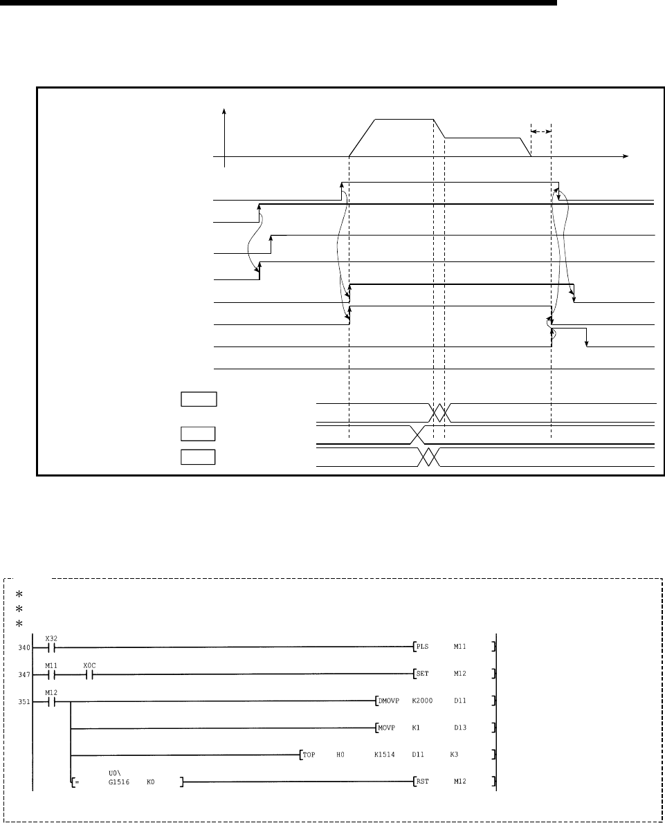
(2) The following shows the speed change time chart.
Cd. 15 Speed change request
Cd. 14 New speed value
In speed change
processing flag
BUSY signal
QD75 READY signal
Error detection signal
V
t
1
0
0
1
0
2000
0
Start complete signal
Dwell time
PLC READY signal
Positioning start signal
Positioning complete signal
[Y10]
[Y0]
[X0]
[X10]
[XC]
[X14]
[X8]
Md. 40
All axis servo ON
[Y1]
Fig. 12.27 Time chart for changing the speed from the PLC CPU
(3) Add the following PLC program to the control program, and write it to the
PLC CPU.
—á
Example
No.14 Speed change program
<Pulsate speed change command>
<Hold speed change command>
<Set speed change value
(20.00mm/min)>
<Set speed change request>
<Write speed change>
<Turn OFF speed change request
memory>


