32 TASCAM 2488MKII
5 − Mixer
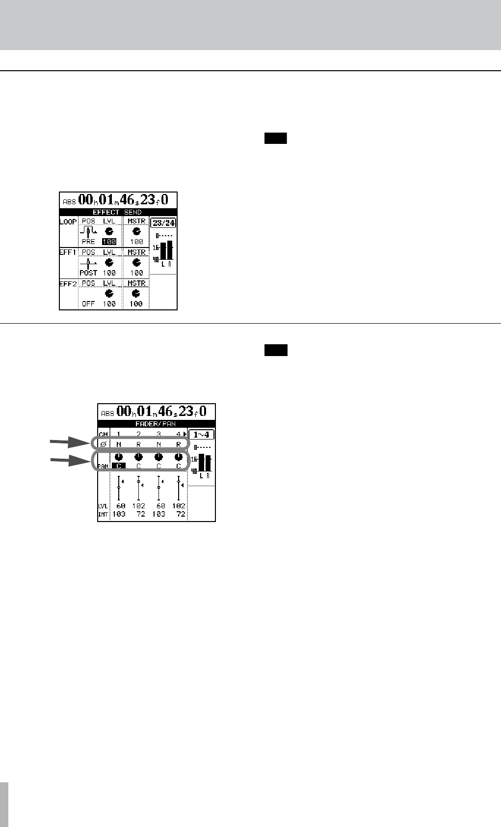
There is one stereo “loop” send (using the internal
effects) in addition two effect sends (using the external
EFFECT SENDS jacks) for each channel. Please see
“Single effect” on page 42 for details about the use of the
internal single effect.
Press the channel’s SELECT key, followed by the SEND
key (this order can be reversed).
For each effect send, there is a soft switch at the left side
of the screen. Use the dial to set this switch either OFF or
POST (post-fader) or PRE (pre-fader).
“Pre-fader” means that the channel fader does not
affect the level of the effect send, as opposed to
“post-fader” where the effect send level is affected
by the channel fader setting.
Set the level of each channel send (LVL) from 0 to 127. This
screen also allows the master send level (MSTR) to be set
(again from 0 to 127).
Effect send
Press the FADER/PAN key to display the FADER/PAN
screen for the current channel. To change the channel,
press the INPUT key or SELECT key of the channel to
change to.
Use this screen to make pan, phase and fader setting for
four channels at a time on this screen (linked channels still
count as two channels here).
Phase
Use this to correct miswired microphones, etc. Out-of-
phase sources can result in unnatural EQ and a “hole in
the middle” stereo effect. The phase symbol (Ø) shows the
current status of the channel: either normal (N) or reversed
(R). Use the cursor keys and dial to change these settings.
Pan
Use PAN parameters to set the stereo position.
In the track channels, this parameter sets the pan positions
of the signals sent to the stereo bus. In the input channels,
it sets the pan positions of signals sent to the sub mix bus.
Full left (“hard left”) is represented by L63, and hard right
by R63. The center position, where the signal is sent equal-
ly to the left and right is represented by C.
ª
ª
With the SHIFT indicator lit, press the PAN key to reset
the highlighted channel’s pan position to the center.
In the case of linked channels, the pan position both
of the highlighted channel and the channel to which it
is linked will be centered.
Faders
The on-screen track channel faders are for display only.
The input channel faders adjust the levels of the signals
sent to the sub mix bus. Select then with the cursor and use
the JOG/DATA dial to set them.
The minimum fader value as shown on screen is 0 (full
cut), and the full level is 127. A level of 100 corresponds to
the “unity gain” position of 0 dB.
In the initial preference settings, the positions of the physi-
cal faders on the top panel and the actual fader levels
(internal fader values) always correspond, but different
fader matching settings may cause the positions and actual
values to differ.
In this case, the Ó next to the fader icon on screen shows
the internal fader position (when the internal fader and
physical fader values are equal, no Ó appears).
See “Scene recall” on page 37 and “Fader matching” on
page 37 for details.
ª
Fader/pan
