


Chapter 7 - Digital Connections
110 Q20 Reference Manual
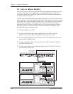
④ Press [<PAGE] until you reach Page 4. The display should read:
INPUT AUDIO SOURCE: A NALOG DATA
⑤ Turn the [VALUE/ENTER] wheel to set the source to ÒS/PDIF DATAÓ.
The ÒDIG INÓ pixel will light in the top left corner of the display and the
ÒSAMPLE CLOCK SOURCEÓ (Page 5) will automatically switch to S/PDIF.
If the ÒDIG INÓ pixel at the top left corner of the display is flashing, this means
that the Q20 is not receiving digital clock. Check your connections and the settings
in your digital mixer to remedy this.
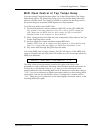
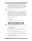
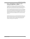
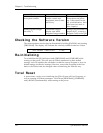
Q20 S/PDIF Out to
Mixer S/PDIF In
Mixer S/PDIF Out to
Q20 S/PDIF In
123456789101112131415161718
To the AI-1
If you wish to route the digital output to a device that uses the AES/EBU standard,
you can connect the Q20 to an Alesis AI-1 (discontinued). This can be done directly,
by connecting the Q20Õs [OPTICAL OUT] to the AI-1Õs ADAT IN or the Q20Õs
[OPTICAL IN] connected to the AI-1Õs ADAT OUT. Alternatively, if you are using
multiple ADATs and the BRC (as described above), you can simply insert the AI-1
into the fiber optic chain, either before or after the Q20.
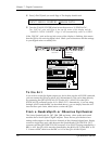
From a QuadraSynth or QS-series Synthesizer
The Alesis QuadraSynth, S4, QS7, QS8, QSR and many other synths and sound
modules have Alesis Optical digital outputs. These devices provide their four
analog audio outputs on the first four channels of the 8 channel digital buss. Simply
connect a single fiber optic cable between the QuadraSynth/QSÕs DIGITAL OUT
connector and the Q20Õs [DIGITAL IN] connector. If an ADAT is being controlled by a
BRC or AI-2, the QS's clock must be controlled by the 48 kHz OUT of the BRC or AI-
2. Connect a BNC cable from the BRC or AI-2 to the QS's 48 kHz IN jack.