


Description of Controls - Chapter 5
Q20 Reference Manual 67
CHAPTER 5
DESCRIPTION OF
CONTROLS
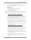
Front Panel
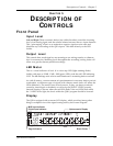
Input Level
Left and Right: These concentric knobs (one within the other) control the incoming
level of our analog signal, and the relative balance between the two input channels.
This Ògain-stagingÓ allows us to maintain a superior signal-to-noise ratio and
eliminate any overloading of the Q20Õs inputs. This feeds directly to the LED
ladder.
Output Level
This controls how much signal we are returning to our mixing console, or whatever
else itÕs connected to. Matching levels throughout the recording/mixing chain will
allow us to get the cleanest possible recordings .
LED Meter
This is a visual indicator of level. It is a four step LED (light emitting diode)
ladder with steps at -32dB, -12dB, -3dB (green LEDs), and the red LED indicating
CLIP. The dB markings refer to how much headroom is remaining before overload.
As with all meters, a certain amount of experimentation is necessary before you feel
comfortable, as different types of signals with sharper attack times will affect the
LEDs differently. The meters have several sources, so they can detect overloads
caused by internal gain or feedback, as well as by the [INPUT LEVEL] controls.
Internal clipping is shown when the red LEDs flash; if the red LEDs flash while
the -3 LEDs do not light, the levels within the Q20Õs program should be lowered.
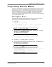
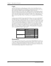
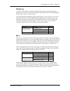
Display
The Q20 is equipped with a custom LCD display, which provides (among other
things) a complete view of the signal routing used by the current Program.
EQ
PCH
DLY
RVB
1
L
M
R
EQ
PCH
DLY
RVB
L
M
R
EQ
PCH
DLY
RVB
L
M
R
EQ
PCH
DLY
RVB
L
M
R
EQ
PCH
DLY
RVB
L
M
R
EQ
PCH
DLY
RVB
L
M
R
EQ
PCH
DLY
RVB
L
M
R
EQ
PCH
DLY
RVB
L
M
R
2
3
4
5
6
7
8
PROGRAM
L
R
IN
L
R
OUT
PRESET
PAG E
16
MIDI
DIG.IN
EDITED
27
38
49
5
Digital Input Indicator
MIDI Input Indicator
Program Number/Status
Page Indicators
Program Blocks/Routing
Alphanumeric Display
Block Pointer