


Description of Controls - Chapter 5
Q20 Reference Manual 79
Rear Panel
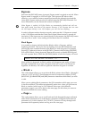
Power
This is a standard IEC-spec power jack for the internal universal power supply.
This supply works with almost any power source worldwide, from 90-265VAC, 50-
60Hz. The Q20 comes with a line cord suitable for the destination to which the
keyboard is shipped.
The AC cord supplied is designed to connect to an outlet that includes three pins,
with the third, round pin connected to ground. The ground connection is an important
safety feature designed to keep the chassis of electronic devices such as the Q20 at
ground potential. Unfortunately, the presence of a third pin does not always
indicate that it is properly grounded. Use an AC line tester to determine this. If the
outlet is not grounded, consult with a licenced electrician.
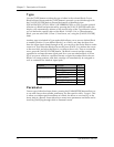
MIDI In
This is a 5 pin DIN standard MIDI plug which connects to any MIDI compatible
equipment such as a MIDI sequencer that will send program changes and controller
information to the unit.
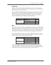
MIDI Thru/Out
This is a 5 pin DIN standard MIDI plug which connects to any MIDI compatible
equipment such as a keyboard or another effects device. Provided for sending system
exclusive commands for storing programs. It also relays all messages received on the
MIDI IN if MIDI THRU is enabled.
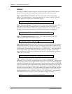
Bypass - Bypass Footswitch
This is a 1/4" phone jack which connects to a footswitch, either normally-open or
normally-closed. When the footswitch is pressed the signal will bypass the effects
chain allowing an instant comparison between the dry and wet signal. The red LED
on the [BYPASS] button on the front panel will illuminate.
Advance - Program Advance Footswitch
This is a 1/4" phone jack which connects to a footswitch, either normally-open or
normally-closed. When the footswitch is pressed the currently selected program
number is advanced by one. When 99 is reached it will roll-over to 00. However, you
can create a range of Programs to be used in conjunction with this footswitch in the
Global menu, page 2. See Footswitch Range, earlier in this Chapter.
48kHz in - Sample Clock Input
This is a BNC connector which connects to an external master clock from an external
device to synchronize digital output. It needs to be used when recording the digital
outputs of the Q20 to an ADAT system that uses either an Alesis BRC or AI-2
synchronizer. Once connected, it is necessary to set the Q20Õs Sample Clock Source to
Ò48kHz INPUTÓ. See Chapter 7 for more information.