


21
Basic Operation
(continued)
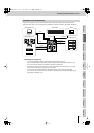
Input/output
settings
Introduction Connections Basic operation Switching images Effects BPM sync External devices Video fader Appendices
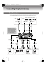
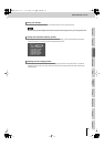
Here’s how to verify that the image is being correctly output to the TV monitor or projector connected to the OUTPUT
connector.
1
Power up your connected equipment and the V-8.
2
Play back your video device.
Input the image from the video device (camera, VTR, DVD player, etc.) or computer.
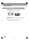
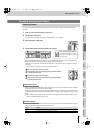
fig.outputfade-up.eps
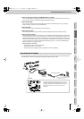
3
Raise the [OUTPUT FADE] fader.
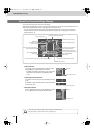
4
Use the INPUT SELECT buttons to switch input channels.
fig.input-select-e.eps
Press the INPUT SELECT button of a channel to which an image is being input. Verify that the image is correctly
shown on the television monitor or projector connected to the OUTPUT connector.
Try switching the input channel, and verify that the image shown in the television monitor or projector is switched
accordingly.
* The input from the S-video connector takes priority for channels 5–8.
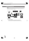
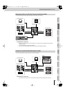
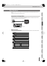
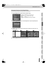
fig.video-fader-e.eps
Move the video fader to the bus A position.
Switch between inputs by successively pressing the INPUT SELECT
[1]–[PC/8] buttons for bus A.
Move the video fader to the bus B position.
Switch between inputs by successively pressing the INPUT SELECT
[1]–[PC/8] buttons for bus B.
When you use the [PC INPUT SELECT] switch to switch the PC input, it will take some time for the input to stabilize.
We recommend that you use a monitor to verify the image.
In addition, selecting the PC input may cause the image display position to be skewed for some computers. Use the
PC input adjustment menu to adjust the screen display position. For details, refer to “Adjusting the PC Input Image”
(p. 54).
* When displaying moving images from a PC input, skew or flickering may occur in the image. For details, refer to
“Skewed or Flickering Images (Tearing)” (p. 55).
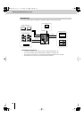
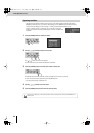
You can output a blue back to the final output image and to the preview of the final output image. Blue back output is
switched on/off using “No Signal Blueback” in the “Utility” menu.
* For details on menu operations, refer to “Menu Operations” (p. 23).
Outputting Images
About the PC inputs
Blue Back Output
Value Details
On
A blue back will be output when there is no signal.
Off
A black image will be output when there is no signal.
Checking the Input and Output
Bus A Bus B
If you’ve selected the [PC/8] button
Use the [PC INPUT SELECT] switch
to change between the PC1 and PC2
connector inputs.
Bus A
Bus B
V-8_e.book 21 ページ 2010年4月16日 金曜日 午後5時14分