


MIDI Implementation
(continued)
96
4. Appendices
■
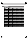
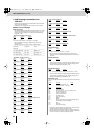
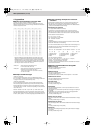
Decimal and hexadecimal conversion table
(The letter “H” follows numbers in hexadecimal notation.)
MIDI uses hexadecimal notation in 7-bit units to indicate data values and
addresses and sizes within an exclusive message. Hexadecimal and decimal
numbers correspond as follows.
+——————+——————++——————+——————++——————+——————++——————+——————+
| Deci | Hexa || Deci | Hexa || Deci | Hexa || Deci | Hexa |
+——————+——————++——————+——————++——————+——————++——————+——————+
| 0 | 00H || 32 | 20H || 64 | 40H || 96 | 60H |
| 1 | 01H || 33 | 21H || 65 | 41H || 97 | 61H |
| 2 | 02H || 34 | 22H || 66 | 42H || 98 | 62H |
| 3 | 03H || 35 | 23H || 67 | 43H || 99 | 63H |
| 4 | 04H || 36 | 24H || 68 | 44H || 100 | 64H |
| 5 | 05H || 37 | 25H || 69 | 45H || 101 | 65H |
| 6 | 06H || 38 | 26H || 70 | 46H || 102 | 66H |
| 7 | 07H || 39 | 27H || 71 | 47H || 103 | 67H |
| 8 | 08H || 40 | 28H || 72 | 48H || 104 | 68H |
| 9 | 09H || 41 | 29H || 73 | 49H || 105 | 69H |
| 10 | 0AH || 42 | 2AH || 74 | 4AH || 106 | 6AH |
| 11 | 0BH || 43 | 2BH || 75 | 4BH || 107 | 6BH |
| 12 | 0CH || 44 | 2CH || 76 | 4CH || 108 | 6CH |
| 13 | 0DH || 45 | 2DH || 77 | 4DH || 109 | 6DH |
| 14 | 0EH || 46 | 2EH || 78 | 4EH || 110 | 6EH |
| 15 | 0FH || 47 | 2FH || 79 | 4FH || 111 | 6FH |
| 16 | 10H || 48 | 30H || 80 | 50H || 112 | 70H |
| 17 | 11H || 49 | 31H || 81 | 51H || 113 | 71H |
| 18 | 12H || 50 | 32H || 82 | 52H || 114 | 72H |
| 19 | 13H || 51 | 33H || 83 | 53H || 115 | 73H |
| 20 | 14H || 52 | 34H || 84 | 54H || 116 | 74H |
| 21 | 15H || 53 | 35H || 85 | 55H || 117 | 75H |
| 22 | 16H || 54 | 36H || 86 | 56H || 118 | 76H |
| 23 | 17H || 55 | 37H || 87 | 57H || 119 | 77H |
| 24 | 18H || 56 | 38H || 88 | 58H || 120 | 78H |
| 25 | 19H || 57 | 39H || 89 | 59H || 121 | 79H |
| 26 | 1AH || 58 | 3AH || 90 | 5AH || 122 | 7AH |
| 27 | 1BH || 59 | 3BH || 91 | 5BH || 123 | 7BH |
| 28 | 1CH || 60 | 3CH || 92 | 5CH || 124 | 7CH |
| 29 | 1DH || 61 | 3DH || 93 | 5DH || 125 | 7DH |
| 30 | 1EH || 62 | 3EH || 94 | 5EH || 126 | 7EH |
| 31 | 1FH || 63 | 3FH || 95 | 5FH || 127 | 7FH |
+——————+——————++——————+——————++——————+——————++——————+——————+
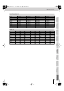
* Decimal expressions used for MIDI channel, bank select, and program
change are 1 greater than the decimal value shown in the above table.
* Hexadecimal values in 7-bit units can express a maximum of 128 levels in
one byte of data. If the data requires greater resolution, two or more bytes
are used. For example, a value indicated by a hexadecimal expression in
two 7-bit bytes “aa bb” would be “aa x 128 + bb.”
<Example 1> What is the decimal equivalent of 5AH?
From the above table, 5AH = 90.
<Example 2> What is the decimal expression of the hexadecimal
expression in two 7-bit bytes “12H 34H”?
From the above table, 12H = 18, and 34H = 52. Thus,
18 x 128 + 52 = 2356
■
Examples of MIDI messages
<Example 1> CEH 49H
CnH is the Program Change status, and n is the MIDI channel number.
EH = 14, and 49H = 73. Thus, this is a Program Change message of MIDI CH=
15, program number 74 (in the GS sound map, Flute).
<Example 2> EAH 00H 28H
EnH is the Pitch Bend Change status, and n is the MIDI channel number.
The second byte (00H=0) is the lower byte of the pitch bend value, and the
third byte (28H=40) is the upper byte. Since the pitch bend value is a signed
value with 40H 00H (= 64 x 128 + 0 = 8192) corresponding to 0, the pitch bend
value in this case is:
28H 00H - 40H 00H = 40 x 128 + 0 - (64 x 128 + 0) = 5120 - 8182 - -3072
If the Pitch Bend Sensitivity is set to two semitones, a pitch change of -8192
(00H 00H) would change the pitch by -200 cents, so in this case, a pitch bend
of -200 x (-3072) / (-8192) = -75 cents is being designated on MIDI channel 11.
■
Exclusive message examples and checksum
calculation
Roland exclusive messages (RQ1, DT1) contain a checksum following the
data (after F7), which can be used to check whether the message was
received correctly. The checksum value is derived from the address and data
(or size) of the transmitted exclusive message.
●
Calculating the checksum
(‘H’ is appended to hexadecimal numbers)
The checksum is a value that produces a lower 7 bits of zero when the
address, size, and checksum itself are summed. If the exclusive message to
be transmitted has an address of aaH bbH ccH and the data is ddH eeH, the
actual calculation would be as follows:
aa + bb + cc + dd + ee = sum
sum / 128 = quotient • • • Eremainder
128 - remainder = checksum
<Example>
Assigning Modulation as the control change that controls the transition effect
time for the “Video Fader” of Tx/Rx Setting.
From the “Parameter address map,” the “Video Fader” of Tx/Rx Setting has a
start address of 01H 10H 0CH, and the Modulation control change has a
parameter value 00H 01H. Thus,
(1) Exclusive status (2) ID number (Roland) (3) Device ID (17)
(4) Model ID (V-8) (5) Command ID (DT1) (6) Address
(7) Data (8) Checksum (9) EOX
Next, we calculate the checksum.
01H + 10H + 0CH + 00H + 01H = 1 + 16 + 12 + 0 + 1 = 30 (sum)
30 (sum) / 128 = 0 (quotient) • • •30 (remainder)
Checksum = 128 - 30 (remainder) = 98 = 62H
Thus, the message to be transmitted is F0H 41H 10H 00H 00H 10H 12H 01H
10H 0CH 00H 01H 62H F7H.
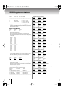
■
Settings Transmitted/Received Using MIDI
●
MIDI Tx Channel
This sets the V-8’s MIDI Transmit channel.
The factory default setting is 1.
●
MIDI Rx Channel
This sets the V-8’s MIDI Receive channel.
The factory default setting is 1.
The values 0-16 can be set via MIDI, which correspond to 1–16 and OFF.
●
MIDI Out/Thru Switch
This sets the MIDI OUT/THRU connector function.
The factory default setting is Thru.
●
V-LINK Switch
This sets the V-LINK On/Off.
The factory default setting is Off.
●
Note Mode
This setting determines whether or not the input is switched when a note on
message is received.
49Keys Mode: You can switch the input with note on message of C+2 [0x24] to
D+4 [0x3E].
Assign Mode: You can switch the input with note on message specified in
“Note Lower Key Assign” to “Note Upper Key Assign.”
The factory default setting is Off.
●
Note Lower Key Assign
This sets the lower limit for note numbers enabled when Note Mode is “Assign
Mode.”
The factory default setting is C+2 [0x24].
●
Note Upper Key Assign
This sets the upper limit for note numbers enabled when Note Mode is “Assign
Mode.”
The factory default setting is D+3
✽
[0x35].
●
Device ID
This sets the ID for distinguishing devices when System Exclusive messages
are received.
The factory default setting is 0x10.
F0H 41H 10H 00H 00H 28H 12H 01H 10H 0CH 00H 01H ??H F7H
(1) (2) (3) (4) (5) (6) (7) (8) (9)
V-8_e.book 96 ページ 2010年4月16日 金曜日 午後5時14分