


9
Input/output
settings
Introduction Connections Basic operation Switching images Effects BPM sync External devices Video fader Appendices
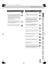
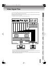
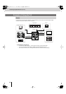
Video Signal Flow
You can use the input selector to choose any two of the video signals coming into the eight input jacks. These two video
signals are sent to
bus A
and
bus B
of the video mixer section.
The video signals sent to bus A and bus B are mixed in the video mixer section. The mixed signal then passes through the
output fader and is sent from the output jack.
☞
For details on the structure of the mixer, refer to “Block Diagram” (p. 108).
fig.signal-flow-e.eps
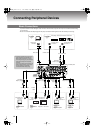
* The preview output will also show the settings menu of the V-8 overlaid with the image (p. 23).
* INPUTs 5–7 provide composite connectors and S-video connectors. If an image is being input to both connectors of the
same channel, the input from the S-video connector will take priority.
* INPUT 8 provides both an S-video connector and a PC connector. If an image is being input to both of these, the input
from the S-video connector will take priority.
Preview output
Input s
elector
Video mixer
Preview selector
Video device Computer
Final output
PREVIEW OUT
INPUT1 INPUT2 INPUT3 INPUT4 INPUT5 INPUT6 INPUT7 INPUT8 PC1 PC2
OUTPUT
Output fader
Inside of the V-8
Bus A
Effects
Fader
Bus B
Effects
Fader
PC input selector
Scan converter
V-8_e.book 9 ページ 2010年4月16日 金曜日 午後5時14分