


97
Input/output
settings
Introduction Connections Basic operation Switching images Effects BPM sync External devices Video fader Appendices
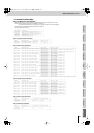
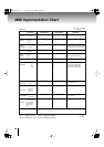
MIDI Implementation
(continued)
●
Input Select A Assign
This controls the bus A INPUT SELECT buttons.
The factory default setting is CC00 + CC32 + PC.
●
Input Select B Assign
This controls the bus B INPUT SELECT buttons.
The factory default setting is CC00 + CC32 + PC.
●
Effect-A1 Assign
This specifies the [1 (FEEDBACK)] button on/off and the parameter.
With the factory settings this is unassigned.
Values are 0, 1–127, corresponding to Off, On: 0–Max.
●
Effect-A2 Assign
This specifies the [2 (NEGATIVE)] button on/off and the parameter.
With the factory settings this is unassigned.
Values are 0, 1–127, corresponding to Off, On: 0–Max.
●
Effect-A3 Assign
This specifies the [3 (COLORIZE)] button on/off and the parameter.
With the factory settings this is unassigned.
Values are 0, 1–127, corresponding to Off, On: 0–Max.
●
Effect-A4 Assign
This specifies the [4 (MULTI)] button on/off and the parameter.
With the factory settings this is unassigned.
Values are 0, 1–127, corresponding to Off, On: 0–Max.
●
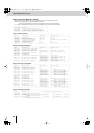
Effect-B1 Assign
This specifies the [1 (FLIP)] button on/off and the parameter.
With the factory settings this is unassigned.
Values are 0, 1–127, corresponding to Off, On: 0–Max.
●
Effect-B2 Assign
This specifies the [2 (CHROMA KEY)] button on/off and the parameter.
With the factory settings this is unassigned.
Values are 0, 1–127, corresponding to Off, On: 0–Max.
●
Effect-B3 Assign
This specifies the [3 (LUMINANCE KEY)] button on/off and the parameter.
With the factory settings this is unassigned.
Values are 0, 1–127, corresponding to Off, On: 0–Max.
●
Effect-B4 Assign
This specifies the [4 (P in P)] button on/off and the parameter.
With the factory settings this is unassigned.
Values are 0, 1–127, corresponding to Off, On: 0–Max.
●
Fade A Switch Assign
This specifies the bus A [FADE] button on/off and the parameter.
With the factory settings this is unassigned.
Values are 0, 1–127, corresponding to Off, On: 0–Max.
●
Fade B Switch Assign
This specifies the bus B [FADE] button on/off and the parameter.
With the factory settings this is unassigned.
Values are 0, 1–127, corresponding to Off, On: 0–Max.
●
Control A Assign
This specifies the bus A [CONTROL] fader output.
With the factory settings this is unassigned.
Values are 0–127, corresponding to 0–Max.
* Transmit only.
●
Control B Assign
This specifies the bus B [CONTROL] fader output.
With the factory settings this is unassigned.
Values are 0–127, corresponding to 0–Max.
* Transmit only.
●
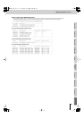
Video Fader Assign
Controls the VIDEO FADER.
The factory default setting is CC11.
Values are 0-127, corresponding to bus A–bus B.
●
Transition Assign
This selects the TRANSITION buttons.
With the factory settings this is unassigned.
Values are 0–2, corresponding to the [1 MIX
], [
2 WIPE
], and [
3 EFX
] button
.
●
Transformer A Assign
This specifies the bus A [RANSFORMER] button on/off.
With the factory settings this is unassigned.
Values are 0–63 and 64–127, corresponding to OFF and ON.
●
Transformer B Assign
This specifies the bus B [RANSFORMER] button on/off.
With the factory settings this is unassigned.
Values are 0-63 and 64-127, corresponding to OFF and ON.
●
BPM SYNC Assign
Switches BPM SYNC on/off.
With the factory settings this is unassigned.
Values are 0-63 and 64-127, corresponding to OFF and ON.
●
Transition Time Assign
This specifies image switching time.
The factory default setting is CC07 (Volume).
Values are 0–127, corresponding to 0.0 sec–4.0 sec.
●
BPM/CONTROL Assign
Controls the [BPM/CONTROL] knob.
The factory default setting is OFF.
* Transmit only.
●
Output Fade Assign
Controls the [OUTPUT FADE] fader.
The factory default setting is OFF.
Values are 0–127, corresponding to fade 0%–100%.
●
White/Black Assign
Controls the [WHITE/BLACK] switch.
The factory default setting is OFF.
Values are 0–63 and 64–127, corresponding to BLACK and WHITE.
●
PC Input Select Assign
Controls the [PC INPUT SELECT] switch.
The factory default setting is OFF.
Values are 0 and 1, corresponding to PC1 and PC2.
●
Preview Output Assign
Controls the PREVIEW OUTPUT SELECT buttons.
The factory default setting is OFF.
Values are 0–1, corresponding to the PREVIEW OUTPUT SELECT [1]–
[OUTPUT] buttons.
●
Memory Assign
Controls the [MEMORY] knob.
The factory default setting is CC00 + CC32 + PC.
Values are 0–7, corresponding to memory number 1–8.
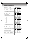
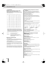
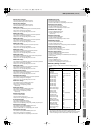
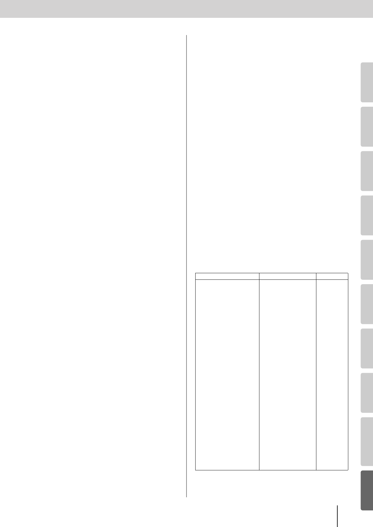
■
Factory Setting of V-LINK
The factory setting of V-LINK (receipt of V-LINK ON message only) is as
follows.
* When V-LINK is off, V-LINK message will be ignored.
* The changes of setting done while V-LINK is on will not be saved.
* When switching from V-LINK ON to OFF, the MIDI transmit/receive settings
revert to the settings that were in effect before V-LINK was switched on.
Parameter Assign Value
Rx Channel - 1
Tx Channel - 1
Note Mode - OFF
Input Select A Assign CC00 + CC32 + PC Bus A: 1
Input Select B Assign CC00 + CC32 + PC Bus B: 2
Effect-A1 Assign OFF OFF
Effect-A2 Assign OFF OFF
Effect-A3 Assign OFF OFF
Effect-A4 Assign OFF OFF
Effect-B1 Assign OFF OFF
Effect-B2 Assign OFF OFF
Effect-B3 Assign OFF OFF
Effect-B4 Assign OFF OFF
FADE A Switch Assign OFF OFF
FADE B Switch Assign OFF OFF
Control A Assign OFF OFF
Control B Assign OFF OFF
Video Fader Assign CC11 (Expression) Bus A 100%
Transition Assign OFF 1
Transformer A Assign OFF OFF
Transformer B Assign OFF OFF
BPM/Sync Assign OFF OFF
Transition Time Assign CC05 (Portamento Time) 0.0sec
BPM CONTROL Assign OFF OFF
Output Fade Assign OFF MAX
White/Black Assign OFF Black
PC Input Select Assign OFF OFF
Preview Output Assign OFF OFF
Memory Assign CC00 + CC32 + PC 1
V-8_e.book 97 ページ 2010年4月16日 金曜日 午後5時14分