


12
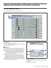
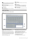
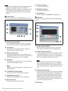
Names and Functions of Controls on Screen
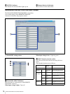
Click “FR” or “EQ” to select the function of equalizer
as the feedback reducer or the parametric equalizer.
FR: The feedback reducer setting screen appears.
When “FR” is selected, the EQ parameter 1 to 5
columns become inactive and FR SETUP button
becomes active.
EQ: The 5-band parametric equalizer setting screen
appears. When “EQ” is selected, the EQ parameter
1 to 5 columns become active and FR SETUP
button becomes inactive.
Note
Changing the parametric equalizer setting will cancel
the howling suppression. When you use the equalizer
as the parametric equalizer, make the setting carefully
not to affect the howling suppression.
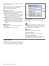
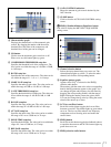
F FR SETUP button
Left-click to display the channel selection dialog box.
With the dialog box, select the channel and click OK
button to carry out the automatic setting of the
feedback reducer (function to suppress the positive
acoustic feedback by detecting the frequency that
causes howling in advance and by reducing the gain of
the frequency).
Note
The FR SETUP button becomes operative only when
the communication between the SRP-X500P Manager
and the mixer is active and “FR” is selected on the FR/
EQ selection radio buttons.
G EQ parameter setup boxes
Set the frequency, Q-value, and gain for each equalizer
band. Values can be set by clicking on the S/s
buttons or by entering numerical value directly.
H CLOSE button
Click to close the MIC INPUT EQUALIZER setting
screen.
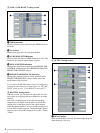
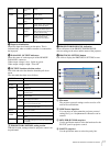
g MUTING button
Left-click to turn muting function on or off. The button
lights up red when it is set to on.
h Input fader
You can adjust the input level by dragging the input fader.
The yellow triangler marker displayed on the side of the
fader indicates the fader position which is the sum of the
input fader setting and the input level control settings on
the mixer.
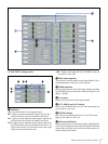
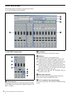
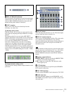
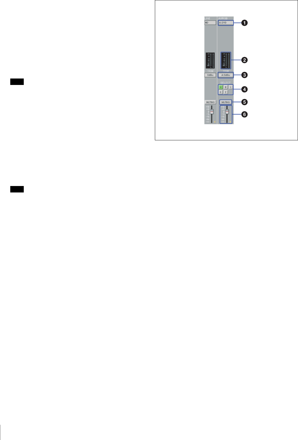
B LINE, AV/RGB INPUT setting section
a Index name indication
Shows the index name of the audio signal input from the
LINE IN connectors or the AV/RGB INPUT connectors
(A to E). For the signal input from the AV/RGB INPUT
connectors, the index name is displayed along with the
SELECT buttons indication (e.g., A:INDEX).
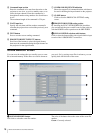
b Level meters
Displays the signal level of each input channel.
c TRIM indication
Displays the reference level of the input channel specified
by the TRIM control on the mixer. For the signal input
from the AV/RGB INPUT connectors, the reference level
is displayed along with the SELECT buttons indication
(e.g., A:–3 dB).
d SELECT buttons
Click to select one of the AV/RGB channels (A to E). The
button for the selected channel lights up green.
e MUTING button
Left-click to turn muting function on or off. The button
lights up red when it is set to on.
f Input fader
You can adjust the input level by dragging the input fader.
The yellow triangler marker displayed on the side of the
fader indicates the fader position which is the sum of the
input fader setting and remote fader setting on the software
and the input level control settings on the mixer.
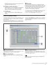
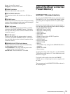
C DELAY indication section