8
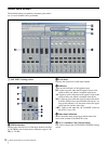
Names and Functions of Controls on Screen
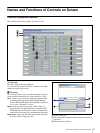
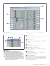
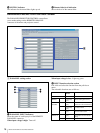
B LINE, AV/RGB INPUT setting section
a TRIM indication
Displays reference level specified by the TRIM control on
the mixer.
b Level meter
Displays the signal level of each input channel.
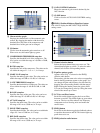
c AV/RGB SELECTOR buttons
Click to select one of the AV/RGB channels (A to E). The
button for the selected channel lights up green.
d SIGNAL DEFINE indication
Displays the signal format specified in the PROJECTOR
CONTROL setting section of the REMOTE PARALLEL/
PROJECTOR CONTROL screen.
e PROJECTOR PROTOCOL indication
Displays the projector protocol setting specified by the
PROJECTOR PROTOCOL selector on the mixer and
model name of the projector.
For details on the MUTING button, fader level indication,
entering the index name for the input signal, see “A MIC
INPUT setting section” of the BLOCK screen (page 7).
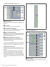
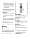
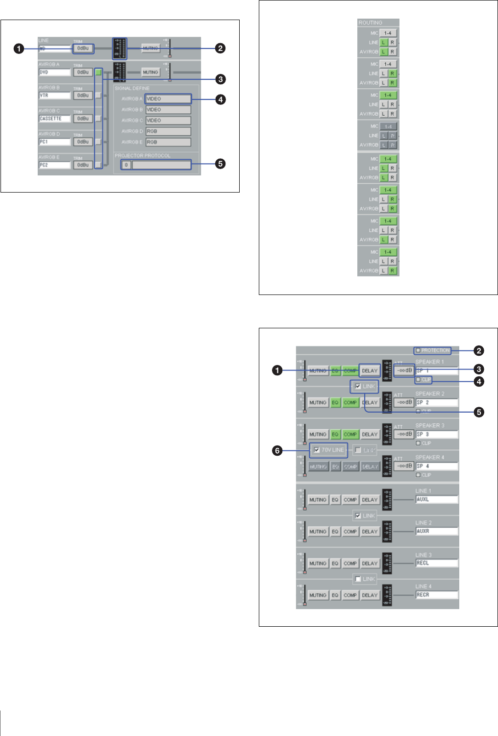
C ROUTING setting section
With this section, you can select an output path for each
input signal by assigning each input channel to an output
channel.
Left-click a channel button to turn the corresponding
channel on or off. Right-click the button to specify the
sending level of the input signal to the output channel.
When the channel button is set to on and the sending level
is set to 0 dB, it lights up green. The button lights up blue
when it is set to on and the sending level is set to –3 dB to
–20 dB.
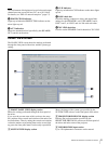
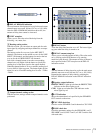
D OUTPUT setting section
a DELAY button
Click to turn the delay on or off. The button lights up green
when the delay is set to on.


