


13
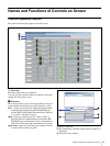
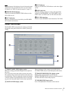
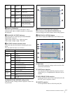
Names and Functions of Controls on Screen
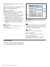
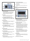
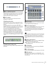
a DELAY REMAIN indication
The total amount of delay time to be set for the total output
channels must not exceed 160 ms (54.7 m, or 181.9 feet).
After the DELAY REMAIN indication shows 0%, the
amount of delay time cannot be increased.
b UNIT setup box
Allows you to select the unit of the delay from the
following: ms, meter, feet.
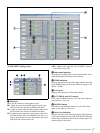
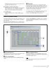
D Routing setting section
With this section, you can select an output path for each
input signal by assigning each input channel to an output
channel.
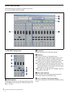
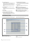
The buttons on the first row are for the MIC INPUT
channels. The buttons on the middle row are for the LINE
INPUT L/R channels, and the buttons located on the last
row are for the AV/RGB INPUT L/R channels.
Left-click a channel button to turn the corresponding
channel on or off. Right-click the button to specify the
sending level of the input signal to the output channel.
When the channel button is set to on and the sending level
is set to 0 dB, it lights up green. The button lights up blue
when it is set to on and the sending level is set to –3 dB to
–20 dB.
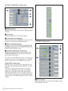
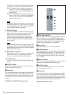
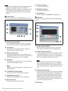
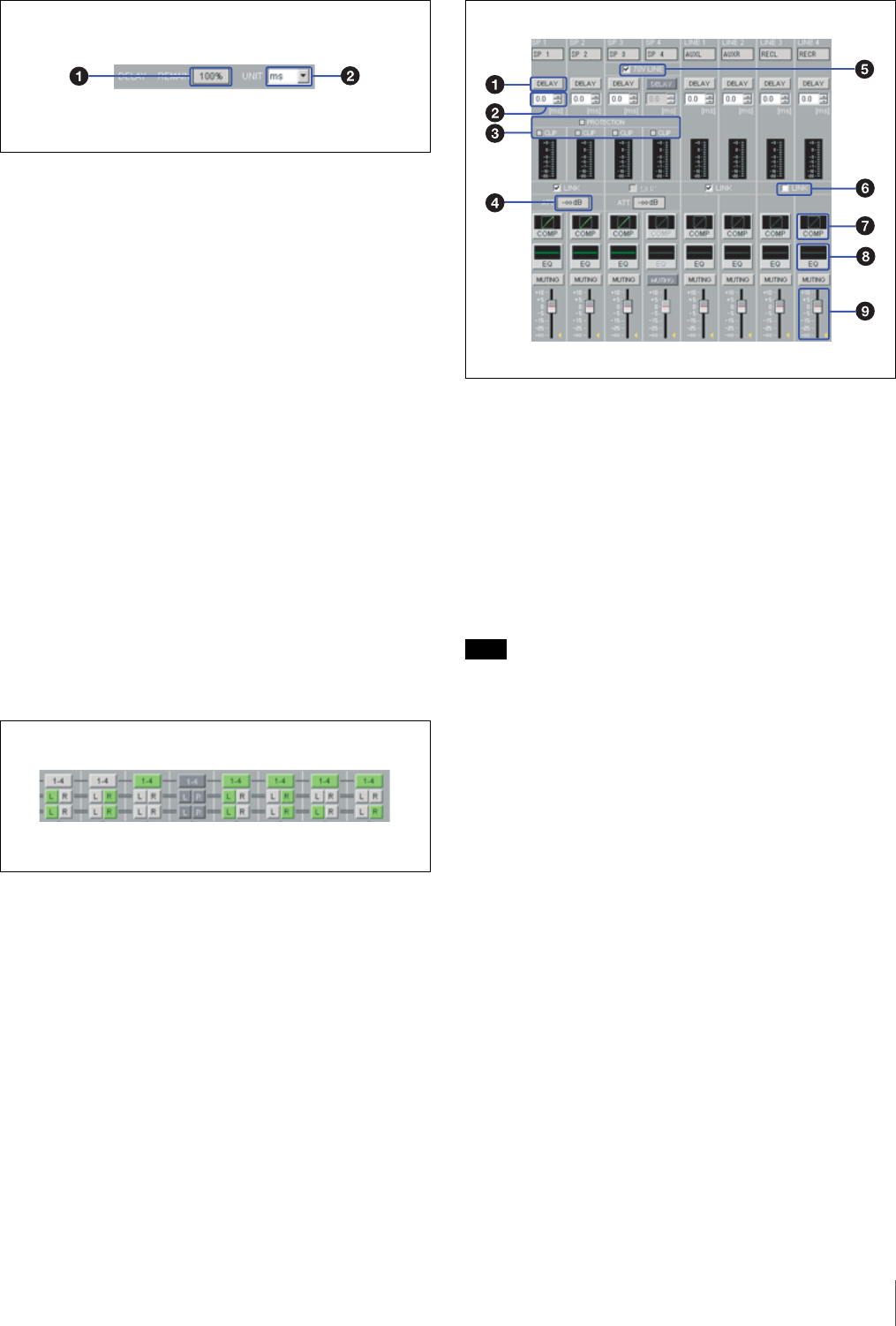
E Output channels setting section
With this section, settings related to output channels can be
performed.
a DELAY button
Turns the delay time function on or off. The button lights
up green when the delay is turned to on.
b DELAY amount setup box
Allows you to select the amount of delay. The value can be
set by clicking on the S/s buttons or by entering
numerical value directly. The amount of delay is shown in
units specified in the UNIT setup box on the DELAY
indication section.
Note
The total amount of delay time to be set for the total output
channels must not exceed 160 ms (54.7 m, or 181.9 feet).
Determine the amount of delay time by watching the
DELAY REMAIN indication on the DELAY indication
section.
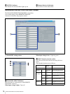
c Speaker output indicators
PROTECTION: Lights up red when the PROTECTION
indicator on the mixer lights up red.
CLIP: Lights up red when the CLIP indicator on the
mixer lights up red.
d ATT indication
Shows the attenuation level specified by the SPEAKER
OUT controls on the mixer.
e 70V LINE check box
Check to set the SPEAKER 3 and 4 channels to 70V LINE.
f LINK check box
Check the parameter settings for the SPEAKER 1 and 2,
SPEAKER 3 and 4, LINE 1 and 2, or LINE 3 and 4 to link
with each other.