


127
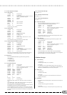
2.1.5 Other Parameter Changes
2.1.5.1 Master Tuning
11110000 F0 Exclusive status
01000011 43 YAMAHA ID
0001nnnn 1n When n is received n=0~F, whichever is received.
When n is transmitted n always=0.
00100111 27 Model ID
00000001 30 Sub ID
00000000 00
00000000 00
0
mmmmmmm
mm Master Tune MSB
0lllllll ll Master Tune LSB
0ccccccc cc
11110111 F7 End of Exclusive
Changes tuning of all channels.
2.1.5.2 Channel Detune
11110000 F0 Exclusive status
01000011 43 YAMAHA ID
0001nnnn 73 Clavinova ID
00111001 39 CVP-79A/69/69A/59S ID
00010001 11 Sub ID
0000nnnn 0n n = MIDI Channel
01000011 43 Dual Detune
0vvvvvvv vv Value vv: $00 - $40 - $7F (-64 - 0 - +63)
11110111 F7 End of Exclusive
The Channel Detune message only affects the specified channel.
2.1.5.3 Volume and Expression Realtime Control Off
11110000 F0 Exclusive status
01000011 43 YAMAHA ID
0001nnnn 73 Clavinova ID
00111001 39 CVP-79A/69/69A/59S ID
00010001 11 Sub ID
0000nnnn 0n n = MIDI Channel
01000101 45 Volume and Expression Realtime Control Off
0vvvvvvv vv Value vv: $00:Off $7F:On
11110111 F7 End of Exclusive
When “On” is received subsequent volume and expression changes are only
valid during key on. Normal operation resumes when “Off” is received.
2.2 Bulk Dump
The CVP 79A/69/69A/59S models support the following parameters.
[XG NATIVE ]
1) XG System Data
2) Multi Effect1 Data
3) Drums Setup Data
2.2.1 XG Native Bulk Data
11110000 F0 Exclusive status
01000011 43 YAMAHA ID
0000nnnn 0n When n is received n=0~F, whichever is received.
When n is transmitted n always=0.
01001100 4C Model ID of XG
0bbbbbbb bbbbbbb ByteCount
0bbbbbbb bbbbbbb ByteCount
0aaaaaaa aaaaaaa Address High
0aaaaaaa aaaaaaa Address Mid
0aaaaaaa aaaaaaa Address Low
00000000 00 Data
||
||
0ccccccc ccccccc Check sum
11110111 F7 End of Exclusive
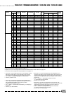
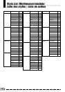
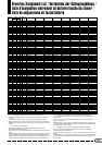
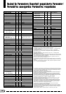
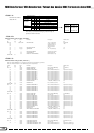
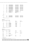
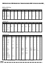
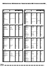
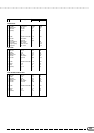
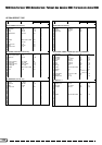
For information about “Address” and “Byte Count” fields, refer to attached
tables.
In the attached tables “TOTAL SIZE” partitions a data series into single bulk
dumps. The “address” is the first byte of the bulk data.
The checksum value is set such that the sum of Byte Count, Address, Data, and
Checksum has value zero in its seven least significant bits.
If too much bulk data is received at a time there is a chance of error. The total
data for a bulk dump should not exceed 512 bytes, it is recommended that data
be kept under 512 bytes with an interval time of 120msec or more between 512
byte bulk.
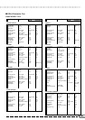
2.2.1.1 XG System Data bulk dump
See Tables 1-1, 1-2.
2.2.1.2 Multi Effect1 Data bulk dump
See Tables 1-1, 1-3.
2.2.1.3 Drums Setup Data bulk dump
See Tables 1-1, 1-5.
2.3 Parameter Request
The CVP 79A/69/69A/59S models support the following request for
parameters covered by Parameter Change specifications.
11110000 F0 Exclusive status
01000011 43 YAMAHA ID
0011nnnn 3n When n is received n=0~F, whichever is received.
When n is transmitted n always=0.
01001100 4C Model ID of XG
0aaaaaaa aaaaaaa Address High
0aaaaaaa aaaaaaa Address Mid
0aaaaaaa aaaaaaa Address Low
11110111 F7 End of Exclusive
If the parameter’s data size is 2 or 4. The Parameter Request address for that
parameter is the first byte of the bulk.
2.4 Dump Request
The CVP 79A/69/69A/59S models support the following request for data
covered by bulk dump.
11110000 F0 Exclusive status
01000011 43 YAMAHA ID
0010nnnn 2n When n is received n=0~F, whichever is received.
When n is transmitted n always=0.
01001100 4C Model ID of XG
0aaaaaaa aaaaaaa Address High
0aaaaaaa aaaaaaa Address Mid
0aaaaaaa aaaaaaa Address Low
11110111 F7 End of Exclusive
For more information on the “Address” field, refer to the attached table.
In the attached tables “TOTAL SIZE” partitions a data series into single bulk
dumps. The “address” is the first byte of the bulk data.
3.Realtime Messages
3.1 Active Sensing
a) Transmission
Transmitted approximately once every 200msec.
b) Reception
If no MIDI data is received within 400ms following receipt of FE, the unit
executes processing equivalent to ALL SOUND OFF, ALL NOTES OFF, and
RESET ALL CONTROLLERS, then clears any remaining FEs.
3.2 MIDI Clock
a) Transmission
Transmitted as 1/96 clocks.
b) Reception
If the [MIDI 1] clock function is set to the External mode it will receive a
resolution of 1/96 clocks.
3.3 Start/Stop
If the [MIDI 2] function Start/Stop filter is ON transmission and reception are
disabled.
a) Transmission
All rhythm start and stop signals are transmitted.
b) Reception
When the relative message is received, the rhythm or song will start or stop.