


106
Assigning channels to the input/output of the recorder
LS9-16/32 Owner’s Manual
Here’s how to patch the desired channels to the input and output of the USB memory recorder.
You can patch any desired output channel or the direct output of an INPUT channel to the
recorder input, and you can patch the recorder output to any desired input channel.
1
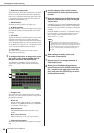
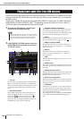
In the DISPLAY ACCESS section, press the
[RECORDER] key repeatedly to access the
RECORDER screen.
In this screen you can assign signals to the input and
output of the USB memory recorder, and perform
recording and playback operations.
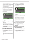
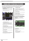
1 RECORDER INPUT field
Here you can make settings for the recorder inputs.
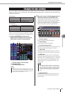
B RECORDER INPUT popup buttons L/R
These buttons access the OUTPUT CH SELECT
popup window, where you can patch channels to the L/
R inputs of the recorder.
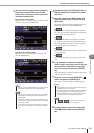
C ATT (attenuator) knob
This knob adjusts the amount of attenuation/boost for
the signal that is input to the recorder. You can adjust
the value in 0.1 dB steps in a range of -96 to +24 dB.
The current value is shown immediately below the
knob.
D Input level meter
This level meter indicates the level of the signal being
input to the recorder.
E INPUT CUE button
This button cue-monitors the signal that is being input
to the recorder. Move the cursor to the button and
press the [ENTER] key to turn cue on/off.
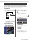
F PLAYBACK OUT field
Here you can make settings for the recorder outputs.
G PLAYBACK OUT popup buttons L/R
These buttons access the INPUT CH SELECT popup
window, where you can patch channels to the L/R out-
puts of the recorder.
H Output level meter
This level meter indicates the level of the signal being
output from the recorder.
I OUTPUT CUE button
This button cue-monitors the signal that is being out-
put from the recorder. Move the cursor to the button
and press the [ENTER] key to turn cue on/off.
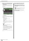
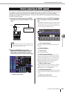
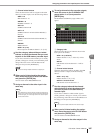
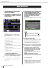
2
To assign channels to the recorder inputs,
move the cursor to the RECORDER INPUT
popup button L or R, and press the
[ENTER] key.
The OUTPUT CH SELECT popup window will
appear.
1 Category tabs
These tabs select the type of channels shown in the
lower part of the window.
● OUT CH
Output channels will be shown.
● CH 1-32 {1-32/33-64}
Direct outputs of INPUT channels 1–32 {1–32/
33–64} will be shown.
Assigning channels to the input/output of the recorder
12 3 4 6
5
8
9
7
1
2
LS9-32