


monitor features
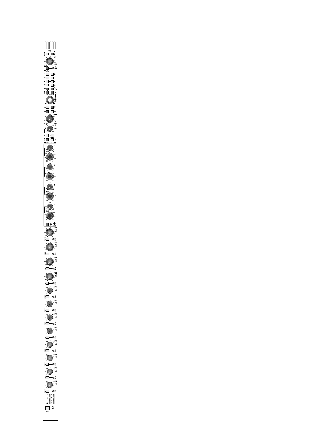
dual 8-segment channel meter
Separately monitors a left and right pre or post fader signal level as deter-
mined by a Master Global POST switch within the master section of the
console. Without this switch depressed, a pre fader signal is monitored.
When the Global master switch is depressed,ALL channel meters switch
to a post fader monitor position to prevent confusion between pre and
post channel metering. The dual 8 segment meters include separate
dynamic signal present LED indicators which vary in intensity to indicate
the presence of any audio signal, and increases in intensity until it reaches
full brightness. When signal level reaches -15dB, an additional LED will illu-
minate. Additional LED’s indicate at channel signal levels of -6db, -3db, 0db,
+3db and +8db.
The left and right red segament LED’s (Top left and right LED) sample sig-
nals at a pre EQ position, post EQ position, and apost fader position.
When these independent signals approaches 3dB of clipping, the associat-
ed LED will illuminate RED. These LED’s are NOT affected by the posi-
tion of the Global Post Fader monitor switch.
VCA-level LED
This LED glows green to indicate the amount of control voltage applied to
the channel VCA; the greater the control voltage, the brighter the LED.
Often, a channel may be assigned to more than one VCA master, and it is
easy to overlook an assignment and wonder why a channel isn’t on.This
LED gives the operator a quick reference to the state of the channel VCA;
if there is no LED indication,there is no VCA control voltage.The LED will
turn from green to red when the control voltage limit of +20dB is reached
as detailed above.This alerts the operator to unusual or incorrect gain set-
tings and prevents any additional fader boost from being applied.
solo switch
Will illuminate when manually selected in one of the consoles many Solo
modes. Controls within the master section determine if this switch will
sample signal pre or post fader/post balance control.
Additional switches will determine the operating characteristics of the
Solo system. These may be selected from within the master section to be
NORMAL (cumulative), LAST PRESSED (Only one switch will be on at a
time.Selecting the next solo switch will automatically cancel the last switch
selected) or MOMENTARY (Solo system on only while switch is held
down). This Solo switch will also Solo and illuminate automatically if the
VCA master group that the channel may be assigned to is put into SOLO.
The STEREO SOLO system displays selected channels on individual Solo
Left and Solo Right meters. The signal also appears on separate
Headphone and Monitor output channels. The solo signal may also be
routed to the Alternate A/B and C/D outputs within the master section.
write-on strip
In the area separating the angled upper portion of the console and the
Fader bay area is a write in strip. This strip the primary module number-
ing, while providing write in area for customer use.
stereo input module
p. 16