


p. 46
master modules—M1, M2
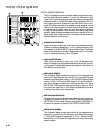
headphone output features
HEADPHONE OUTPUT CONNECTORS - 1/4” headphone connector
under the arm rest area as well as on the top module panel.
HEADPHONE INSERT CONNECTORS - Separate left and right insert
send and return connectors for the purpose of inserting external delay
devices. In addition, as these points are located after the master head-
phone level control, the insert send can be used to feed an external high-
er powered amplifier.
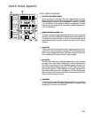
line 1 input-switch
Monitor source of XLR Stereo Pair of balanced line level inputs to head-
phones.
line 2 input-switch
Monitor source of XLR Stereo Pair of Balanced line level inputs to head-
phones.
line 3 input-switch
Monitor source of 1/4” Balanced/Unbalanced line level inputs in mono or
stereo to headphones. If only a single connector is plugged in, signal is
monitored in mono.
line 4 input-switch
Monitor source of 1/4” Balanced/Unbalanced line level inputs in mono or
stereo to headphones. If only a single connector is plugged in, signal is
monitored in mono.
mono-output switch
Monitors mono output signal to headphones.
left-/right-output switch
Monitors left and right output signals to headphones.
LCR output-monitoring
When both Left/Right and Mono switches are depressed,a LCR signal mix
can be monitored on headphones.
external talkback-in
Allows direct monitoring of the external talkback input (closed loop sys-
tem) on headphones.