


10
En
Connections
! Connect the power cord after all the connections between devices have been completed.
Be sure to turn off the power and unplug the power cord from the power outlet whenever making or changing connections.
Refer to the operating instructions for the component to be connected.
! Be sure to use the included power cord.
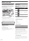
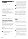
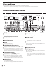
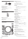
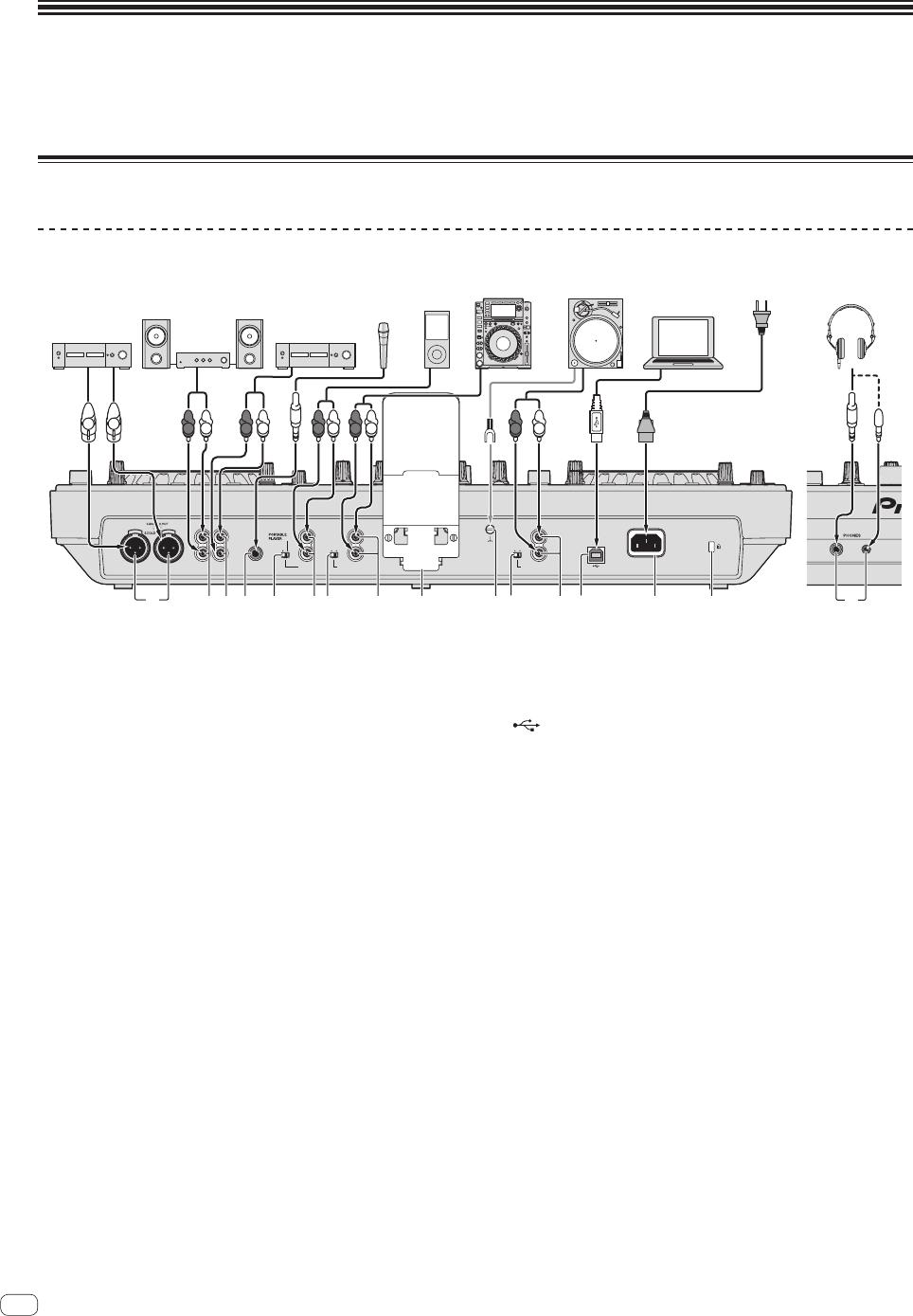
Connecting the input/output terminals
Rear panel, front panel
MIC
BOOTH
OUT
MASTER
OUT 2
L
R
L
RRL
MASTER OUT 1
PHONOLINE
PHONO 2 / LINE 2
L
R
LINE
AUX IN
0 dB
L
R
12 dB
USB
AC IN
SIGNAL
GND
PHONOLINE
PHONO 1 / LINE 1
L
R
4
1
3
2
5 7 986
a7 b8
c d
e
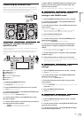
Rear panel Front panel
R
L
R
L
Microphone
Power amplifier,
powered speakers,
etc.
Power amplifier
(for booth monitor)
R
L
R
L
DJ player
Portable audio
device
R
L
Headphones
To power outlet
Analog player
DJ
software
Computer
R
L
Power amplifier,
powered speakers, etc.
1 MASTER OUT 1 terminals
Connect a power amplifier, powered speakers, etc., here.
Be sure to use these as balanced outputs. Be careful not to acci-
dentally insert the power cord of another unit.
2 MASTER OUT 2 terminals
Connect a power amplifier, powered speakers, etc., here.
3 BOOTH output terminal
This is an output terminal for a booth monitor.
4 MIC jack
Connects a microphone here.
5 LINE, PORTABLE PLAYER selector switch
Switch this according to the audio level input to the [AUX] terminals.
6 AUX IN terminals
Connect a line level output device (such as a DJ player) or a device
with a low gain (such as a portable audio player) here. Switch the
terminals’ input gain according to the connected device using the
[LINE, PORTABLE PLAYER] selector switch on this unit’s rear panel.
7 LINE, PHONO selector switch
Switches the function of the [PHONO/LINE] terminals.
8 PHONO1/LINE1 and PHONO2/LINE2 terminals
Connect a phono level output device (analog player (for MM car-
tridges), etc.) or a line level output device (DJ player, etc.) here.
Switch the terminals’ function according to the connected device
using the [LINE, PHONO] selector switch on this unit’s rear panel.
9 Smartphone stand
A mobile device can be set here.
For instructions on mounting the smartphone stand, see Mounting
the smartphone stand on page 4.
a SIGNAL GND terminal
Connects an analog player’s ground wire here. This helps reduce
noise when the analog player is connected.
b USB terminal
Connect to a computer.
! A USB hub cannot be used.
! To maintain performance, use with this unit and the computer
connected directly using the included USB cable.
c AC IN
Connect this to a power outlet.
Connect the power cord after all the connections between devices
have been completed.
Be sure to use the included power cord.
d Kensington security slot
e PHONES jacks
Connect headphones here.
Both stereo phone plugs (Ø 6.3 mm) and stereo mini phone plugs (Ø
3.5 mm) can be used.
! There are two output terminals (one for a stereo phone jack and
one for a mini-phone jack), but do not use both terminals simulta-
neously. If one is connected or disconnected while the other one
is being used, the volume of the other one in use may increase or
drop suddenly.