13
Panel Description
Panel Description
Panel Description
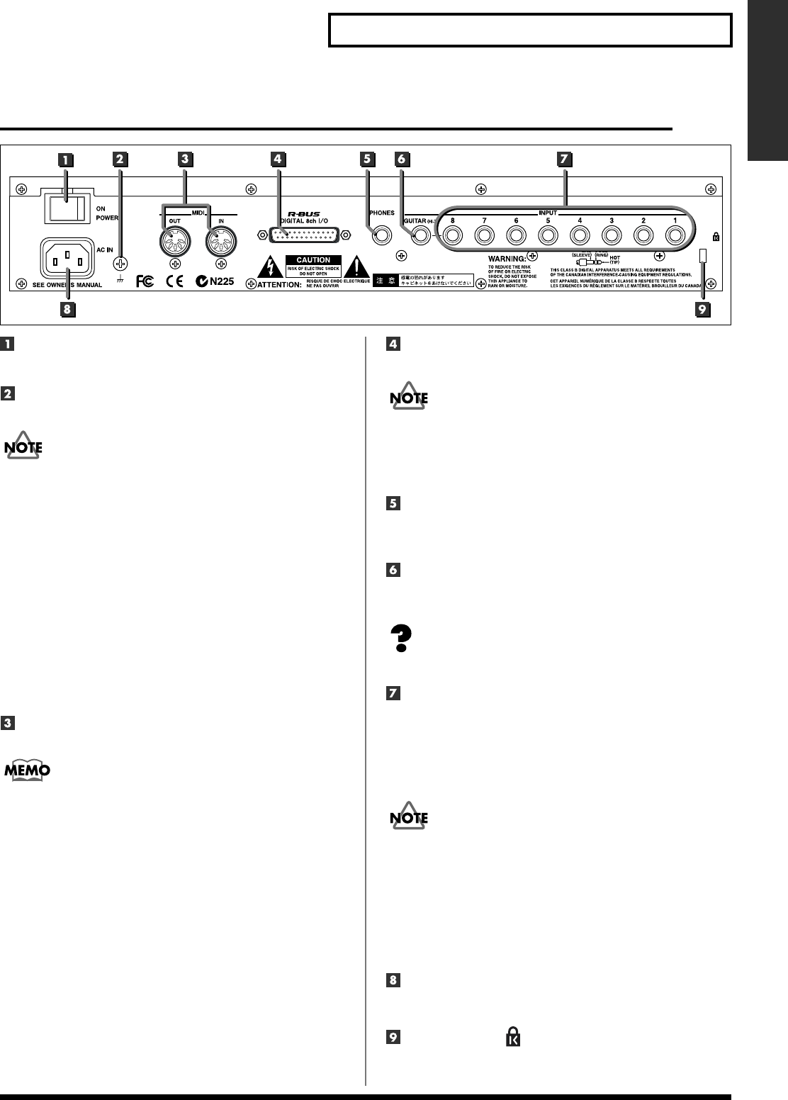
Rear panel
Power switch
Turns the power on/off.
Earth Connector
Connect the ground cable here.
In some cases, depending on the environment in which the unit is
installed, the surface of the panel may sometimes feel rough and
grainy. This is due to an infinitesimal electrical charge, which is
absolutely harmless. However, if you are concerned about this,
connect the ground terminal (see figure) with an external ground.
When the unit is grounded, a slight hum may occur, depending on
the particulars of your installation. If you are unsure of the
connection method, contact the nearest Roland Service Center, or an
authorized Roland distributor, as listed on the “Information” page.
Unsuitable places for connection
• Water pipes (may result in shock or electrocution)
• Gas pipes (may result in fire or explosion)
• Telephone-line ground or lightning rod (may be dangerous in the
event of lightning)
MIDI connectors (IN, OUT)
Connect a MIDI sequencer or other external MIDI device here.
In order for a MIDI device connected to the SI-24 to be controlled via
the MIDI connector, you must switch MIDI Control Mode on. For
details, refer to “Using the MIDI connectors to transmit/receive
control data—MIDI Control Mode” (p. 29).
● IN
This connector receives MIDI messages from another MIDI
device. Connect it to the MIDI OUT connector of the external
MIDI device.
● OUT
This connector transmits MIDI messages. Connect it to the
MIDI IN connector of the external MIDI device.
R-BUS connector
Use this connector to connect the SI-24 and RPC-1.
• You must use a special R-BUS cable to make this connection.
The SI-24 cannot use a five meter R-BUS cable (RBC-5).
• The R-BUS connector of SI-24 can not be used by connecting with
the equipment requires power supply via R-BUS such as DIF-AT,
VE-7000 and so on.
PHONES jack
A set of stereo headphones can be connected here.
* This jack will output the same sound as MASTER L/R.
GUITAR jack
This is a high-impedance jack. An electric guitar or bass can be
connected directly to this jack.
Impedance (p. 46)
INPUT jacks 1–8/phone type
These jacks allow devices with phone plugs to be connected.
The audio signals that are input to INPUT 1–8 of the SI-24 are
sent to “R-Bus In 1–8” of the RPC-1.
* These are TRS phone jacks that allow either balanced or unbalanced
connections.
• You cannot use the GUITAR jack and the INPUT 8 jack (phone
type/XLR type) simultaneously. If devices are connected to both
jacks, the GUITAR jack input will take priority. If you want to use
the input from the INPUT 8 jack (phone type/XLR type), do not
connect anything to the GUITAR jack.
• Do not connect plugs to both the XLR type and phone type
INPUT jack of the same number.
• When using the phone type INPUT jack, you must switch
phantom power off.
AC inlet
Connect the power supply cable to this inlet.
Security Slot ( )
You can lock this product using ordinary sold security wire
etc. See “http://www.kensington.com/” for details.


