15
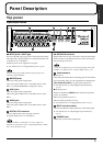
Preparing to use the SI-24
Preparing to use the SI-24
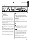
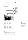
• Do not connect plugs to both the XLR type and
phone type INPUT jack of the same number.
• You cannot use the GUITAR jack and the INPUT 8 jack
(phone type/XLR type) simultaneously. If devices are
connected to both jacks, the GUITAR jack input will take
priority. If you want to use the input from the INPUT 8
jack (phone type/XLR type), do not connect anything to
the GUITAR jack.
• If using the phone type INPUT jack, you must switch
phantom power off. For details, refer to “Using phantom
power” (p. 16).
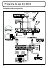
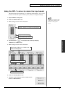
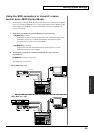
• In order to handle audio with the SI-24 and to transfer
audio between the SI-24 and your computer, you must
connect it to a computer in which an R-BUS interface card
(RPC-1) has been installed.
•
You must use a special R-BUS cable to make this connection.
The SI-24 cannot use a five meter R-BUS cable (RBC-5).
•
The R-BUS connector of SI-24 can not be used by connecting with
the equipment requires power supply via R-BUS such as DIF-AT,
VE-7000 and so on.
• To prevent malfunction and/or damage to speakers or
other devices, always turn down the volume, and turn off
the power on all devices before making any connections.
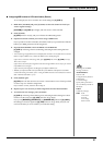
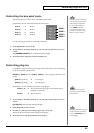
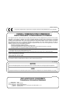
• This instrument is equipped with balanced (XLR/TRS)
type input jacks. Wiring diagrams for these jacks are
shown below. Make connections after first checking the
wiring diagrams of other equipment you intend to
connect.
• Howling could be produced depending on the location of
microphones relative to speakers. This can be remedied
by:
1. Changing the orientation of the
microphone(s).
2. Relocating microphone(s) at a greater
distance from speakers.
3. Lowering volume levels.
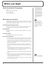
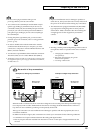
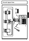
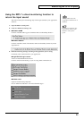
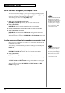
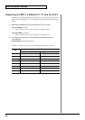
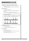
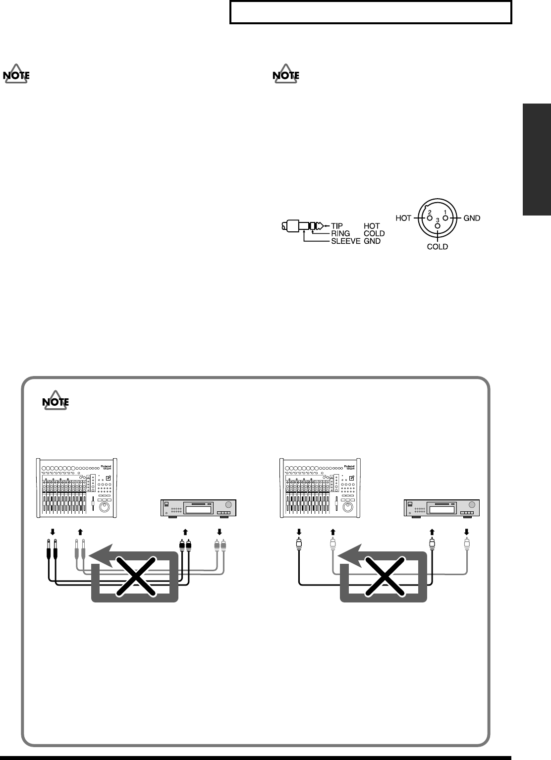
Be careful of loop connections
fig.3-2e
When the SI-24 is connected as shown in the above diagram to a device that passes the input sound through
to its output (a DAT recorder/the Roland VS series that is recording), the SI-24 and that device will form a
loop that can cause oscillation, producing an unexpectedly loud sound.
This type of connection can cause malfunction and damage to speakers and other equipment; take care to
avoid these conditions.
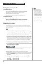
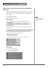
In addition to the above figure, take a moment now to check your connections for the following conditions.
• Could there be a looped connection between the analog and digital realms?
• Has any looped connection resulted from insertion of a mixer or other piece of equipment between the
devices?
Example of an Analog Loop Connection Example of a Digital Loop Connection
OUTPUT INPUT
SI-24
LINE OUTLINE IN DIGITAL OUT DIGITAL IN
SI-24
MD Recorder/
VS series etc.
MD Recorder/
VS series etc.
DIGITAL OUTDIGITAL IN