


Setting up the SDC 8200 system
57
tem installed in a separate room to carry out a remote conference. The par-
ticipants of both conferences can then participate in a common confer-
ence.
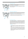
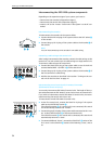
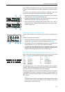
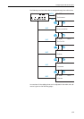
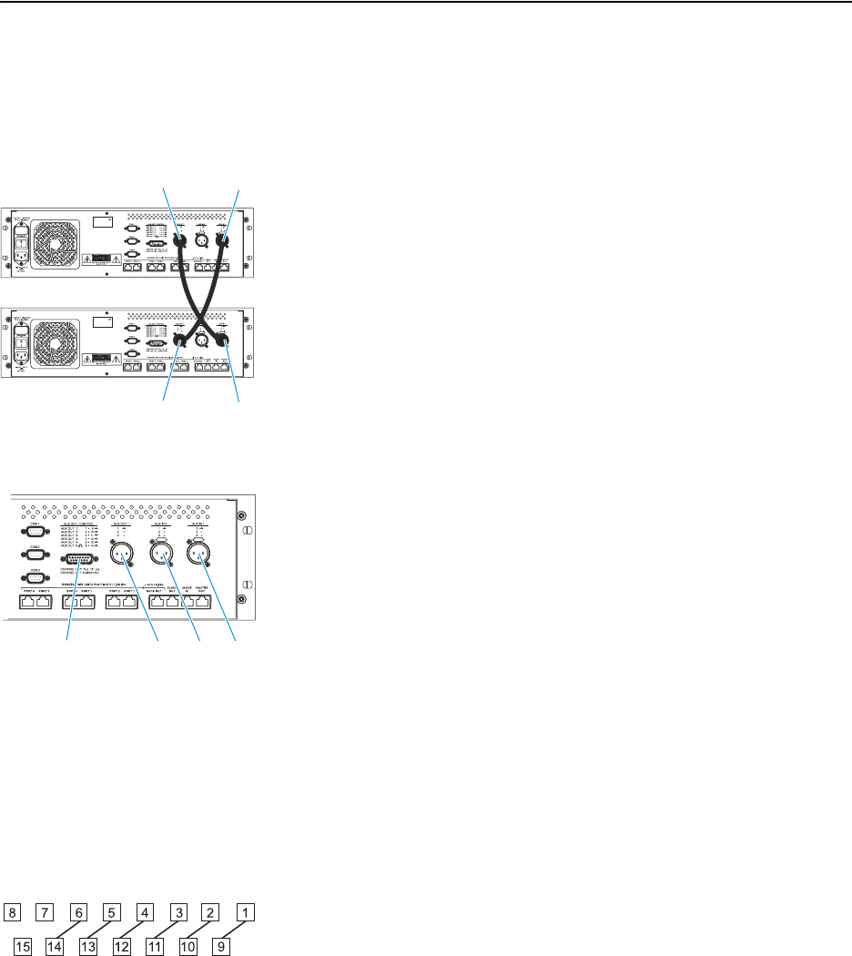
To connect two conference systems installed in separate rooms, you
require two XLR cables with two XLR-3 connectors respectively:
̈ Connect the audio input AUX IN 1 º of the first central unit to the audio
output AUX OUT 1 µ of the secend central unit.
̈ Connect the audio input AUX IN 1 º of the secend central unit to the
audio output AUX OUT 1 µ of the first central unit.
̈ From the central unit’s operating menu, choose “
Dist. Conf. = ON” to
prevent echo (see “Configuring the audio outputs for remote confer-
encing” on page 107).
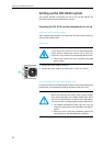
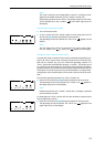
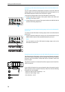
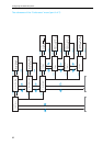
Connecting PA systems, recording units, etc.
Via the audio outputs you can connect e.g. a PA system, a recording unit,
etc.
Connect the desired unit as follows:
̈ The signals of the floor channel are available at the XLR-3M audio out-
put AUX OUT 1 µ and the 15-pole sub-D socket AUX OUT 2 ƺ.
̈ The signals of up to four interpretation channels are available at the
outputs AUX OUT 2-3-4-5-6 ƺ of the 15-pole sub-D socket.
̈ If an SDC 8200 AO analog output unit is connected to the DATA OUT
socket ƹ of the SDC 8200 CU central unit, additional channels can be
output via the analog output unit’s XLR-3M audio outputs.
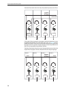
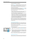
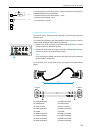
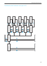
Pin assignment of the 15-pole sub-D socket (AUX OUT 2-3-4-5-6)
When connecting external equipment to the 15-pole sub-D socket (AUX
OUT 2-3-4-5-6 ƺ), please observe the following pin assignment:
The audio signal of the floor channel is always available at the two outputs
AUX OUT 1 (XLR-3M audio output) and AUX OUT 2 (pin 2 and 10 of the 15-
pole sub-D socket). This assignment cannot be changed!
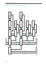
The channel assignment for the four other audio outputs can be changed
as described in the section “Assigning a channel to an audio output” on
page 105. You can assign these outputs any interpretation channel or the
floor channel.
Note!
The audio signal of the channel assigned to the output AUX OUT 6 (pin
6 and 14 of the 15-pole sub-D socket) is also available at the head-
phone output of the central unit!
º
µ
µ
º
ƺ º¾µ
PIN SIGNAL
1+9 Aux Out 1
2+10 Aux Out 2
3+11 Aux Out 3
4+12 Aux Out 4
5+13 Aux Out 5
PIN SIGNAL
6+14 Aux Out 6
7not assigned
8not assigned
15 not assigned