


Setting up the SDC 8200 system
59
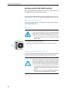
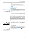
If you connect DC sources such as e.g. a relay coil, make sure that the fol-
lowing limitations are not exceeded!
y Maximum load current (alternating) = 1.8 A
y Maximum load voltage = 60 V
y On-resistance = 0.15 Ω
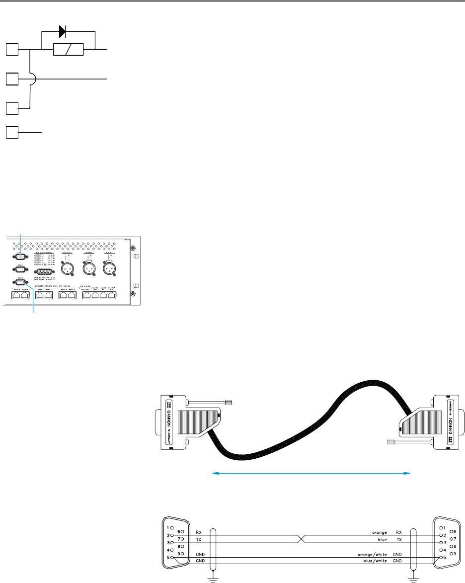
Connecting a PC to the central unit
You require one PC with two serial interfaces or two PCs with one serial
interface each.
To control the conference and interpretation system via one or two PCs
using the SDC 8200SYS/SDC 8200SYS-M software:
̈ Connect one serial interface to the COM 3 interface · of the central
unit to control the conference system.
̈ Connect the other serial interface to the COM 1 interface ³ of the cen-
tral unit to control the interpretation system.
Note!
If you are using more than one central unit, the PC has to be connected
to the “master” central unit.
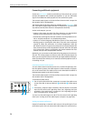
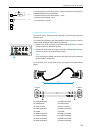
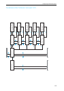
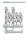
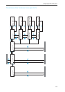
For connecting a PC to the central unit, you require the cables shown
below:
1
2
3
4
+ Vdc
- Vdc
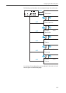
·
Pin 1:Not connected
Pin 2:RX Receive
Pin 3:TX Transmit
Pin 4:Not connected
Pin 5:GND
Pin 6:Not connected
Pin 7:Not connected
Pin 8:Not connected
Pin 9:Not connected
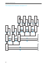
Pin 1:Not connected
Pin 2:RX Receive
Pin 3:TX Transmit
Pin 4:Not connected
Pin 5:GND
Pin 6:Not connected
Pin 7:Not connected
Pin 8:Not connected
Pin 9:Not connected
PC SUB-D F
PC SUB-D F
15 m