


Getting Started
VX4380 256-Crosspoint Relay Matrix Module User Manual
1–5
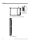
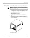
The following LEDs are visible at the top of the VX4380 Module’s front panel to
indicate the status of the module’s operation (see Figure 1–5).
Power LED indicates power is applied to the module
Failed LED indicates the module is in the FAILED state
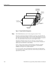
Built-in Test Equipment (BITE) is provided by extensive self tests that are
automatically invoked on power-on and can also be invoked on command.
Circuitry tested includes the CPU and all memory
, and the relay control circuitry
on each relay module controlled by the Option 01.
Accessories
Table 1–1 lists the standard accessories included with the VX4380.
Table 1–1: Standard Accessories
Accessory Part Number
VX4380 User Manual 070-9182-XX
VX4380 Reference 070-9202-XX
Table 1–2 lists the options available for the VX4380.
Table 1–2: Options
Option Part Number
01 VXI Interface Kit 040-1510-XX
Controls and Indicators
The following controls are provided to select the functions of the VX4380
operating environment. Figures 1–3 and 1–4 illustrate the physical location of
these controls and indicators.
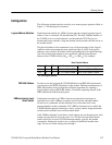
The Logical Address switches and
VMEbus Interrupt Level Select switch must be
correctly set to insure proper operation. See Configuration for details on how to
set the switches.
LEDs
BITE (Built-in Test
Equipment)
Switches