


51
Basics Section
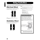
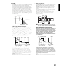
● FILTER
In PAGES 13 to 22, you can use the filter to change
the tonal characteristics of each Element, by
adjusting overtones (harmonic tones) included in
the waveform from the Element. The S03 employs
an LPF (low pass filter). Only frequencies below
this point are passed. You can also set the Filter
Envelope Generator (FEG) for time variance of how
the filter works, which results in a dynamic change
in tonal characteristics. Here, we’ll show you how
the FEG works.
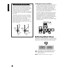
FEG (Filter Envelope Generator)
Using the FEG, you can control the transition in
tone from the moment a note is pressed on the
keyboard to the point at which it is released. When
you press a note on the keyboard, the cutoff
frequency will change according to these envelope
settings. This is useful for creating automatic wah
effects, for example. Furthermore, different FEG
parameters can be set for each Element.
In the illustration, the letters a - d indicate the
respective Rate (R) settings for Attack - Release.
The greater the value for each Rate, the faster the
filter goes to the next set Level — in other words, the
time it takes for the filter to change (between Level
settings) becomes shorter.
n For details about the FEG parameters, see page 79.
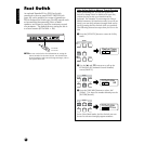
● AMP (Amplitude)
In PAGES 23 to 31, you can set the volume of each
Element after the OSC (Oscillator), PITCH and
FILTER parameters have been applied, as well as
the final overall volume of the signal sent to the
outputs.
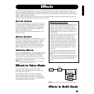
The signal of each Element is sent at the specified
volume to the next Effect section.
Also, by setting the AEG (Amplitude Envelope
Generator), you can control how the volume
changes over time.
n
The final volume for all Elements is set in the Total
Vol (Total Volume) parameter, Common Edit PAGE 2.
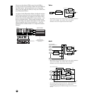
AEG (Amplitude Envelope Generator)
By using the AEG, you can control the transition in
volume from the moment a note is pressed on the
keyboard to the point at which it is released. When
you press a note on the keyboard, the volume will
change according to these envelope settings.
Furthermore, different AEG parameters can be set
for each Element.
In the illustration, the letters a - d indicate the
respective Rate (R) settings for Attack - Release.
The greater the value for each Rate, the faster the
volume goes to the next set Level — in other words,
the time it takes for the volume to change (between
Level settings) becomes shorter.
n For details about the AEG parameters, see page 80.
Frequency
Cutoff Frequency
Level
Cutoff range
Range passed
Volume
0
Release
Level
Attack
Level
Attack
Time
Initial
Level
Decay1
Time
Decay2
Time
Release
Time
a
b
c
d
Decay1
Level
Sustain
Level Key off
Time
Level
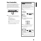
EffectAMPFILTPITCH
OSC
Element
1~4
PEG FEG
AEGLFO
0
Release
Level
Attack
Level
Attack
Time
Initial
Level
Decay1
Time
Decay2
Time
Release
Time
a
b
c
d
Decay1
Level
Sustain
Level Key off
Time
Volume