


ARTURIA – MOOG MODULAR V 2.6 – USER’S MANUAL 61
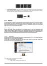
6.4 U
SING CABLES
The connection of different modules is the base work of creating a new patch. The Moog
Modular V owes its creative possibilities in no small part to the innumerable connections
possible between modules. On the original system, all of the connections were made with
cables of two types:
Audio and modulation cables (which allow for example the connection of an oscillator
sawtooth signal to a filter input).
The trigger cables (which allow for example the connection of the keyboard to auxiliary
envelopes). The trigger cables transport trigger information for envelopes or the sequencer
for example.
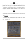
In the Moog Modular V, for ergonomics and graphical readability, only part of the connections
is displayed on the screen in cable form. The other connections are made either by menus, or
with digital displays on which we can click.
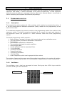
The different types of connections we can use on the Moog Modular V are as follows:
Audio connections / modulation connections: these connections are made with cables that are
visible on the screen.
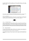
Trigger connections: these connections are only done through menus.
Synchronization connections: these connections are only done through menus.
Key follow or sequencer connections: these connections are available and can be modified
through visible digital displays on the filters and drivers modules.
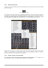
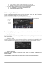
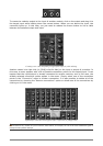
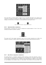
6.4.1 Audio and modulation connections
The audio connections allow, for example, the routing of a sound to the VCA/mixers or to the
inputs of different filters. The modulation connections allow, for example, routing of an LFO
output or an envelope generator to an oscillator PWM or VCA modulation input. These audio
and modulation signals are totally compatible, the only difference being that the audio signals
are “audible” if you connect them directly to an output VCA, while the modulation signals are
generally not audible (as the frequency is too low for the human ear). Modulation signals are
thus generally used to program “slow” variations on certain synthesis parameters, like the cut-
off frequency of a filter for example.
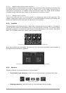
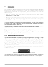
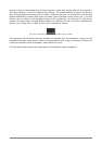
The audio output and input connectors, and the modulation output connectors are identical in
the graphical interface:
Audio input or output connectors, or modulation output connectors
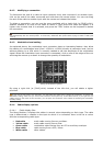
The modulation input connectors are graphically distinguished from the other connectors as
they include an extra function: a modulation level setting, described later in this paragraph.