


80 ARTURIA – MOOG MODULAR V 2.6 – USER’S MANUAL
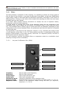
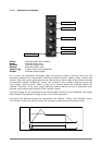
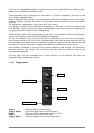
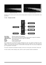
Frequency Sets the oscillation frequency
Delay Delay time setting after a keyboard trigger
Mode Choice of frequency setting: low, mid, synchronized on the MIDI tempo
Fade in Sets the time constant for the increase of modulation
Width Sets the impulse width
PWM Input Input connection for the impulse width modulation
FM Input Frequency modulation input connection
Outputs Connection jacks for the different outputs
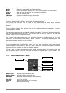
The use of a low frequency generator as a modulation source is typical. It allows the gentle
evolution of the tone of a sound or to simulate vibrato and tremolo.
Even though the oscillators can be used at very low frequencies, there are 2 modules
specifically for this purpose, which allow the oscillators to be kept for use in the audible
domain.
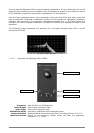
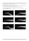
These oscillators possess five outputs that can be used simultaneously: sawtooth, sinusoid,
triangle, square, random.
The oscillation frequency can be statically set with the rotating “frequency” button dynamically
with the associated modulation input. The impulse width can also be statically set with the
“width” button and by its modulation input.
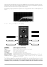
The “mode” interrupter synchronizes the oscillation frequency with the tempo of the host
sequencer. In this mode, the rotating button chooses a frequency depending on the
application’s tempo (multiple or sub multiple).
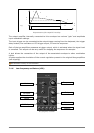
Two other buttons are affecting a delay and a fade in at the output of this generator. Initialized
on a keyboard trigger, the generator output will only begin to oscillate when the internal
counter reaches a time value set with the “delay” knob. This oscillation wills gently increase
following the time constant set with the rotating “fade in”.
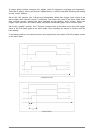
There is also an output generating a trigger signal synchronous with the square signal and
with an identical width, which lets us trigger envelopes and sequencer in a cyclic manner. This
output is visible only visible at trigger input menu level.
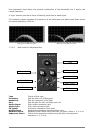
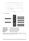
7.1.7 Controlled amplifiers / Mixers
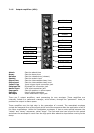
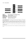
Controlled amplifier (VCA)
Audio Input Amplifier input connection jack
Audio Output Amplifier output connection jack
AM Input Amplitude modulation input connection jack
Volume Input gain setting
Soft Clip Use of soft clipping
Inverse Request inversion of the input signal
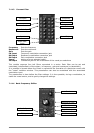
Link Next amplifier mixing
Link
Volume
Audio Output
AM Input
Soft Clip
Inverse
Audio Input