


ARTURIA – MOOG MODULAR V 2.6 – USER’S MANUAL 69
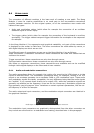
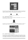
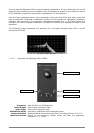
The controller is for the management of the impulse frequency and width of the 3 slave
oscillators. It can be used either statically with the knobs or thanks to the modulation inputs,
which can be connected to the output of any module (envelope, oscillator, modulation dial…).
The slave oscillators can equally be tuned and modulated separately with a knob and a range
selector. These oscillators provide four waveforms that can be used simultaneously.
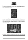
This method of organizing the oscillators, typical of Moog modular synthesizers, helps to
rapidly obtain a very rich tone. The tree oscillators tuned separately and waveforms mixed give
very dense tones. This tone can then easily be modulated with the controller. Adding a vibrato
effect on this sonority is immediate using a modulation input of the controller. This would not
be the case if each of the modulation inputs of the slave oscillators had to be set.
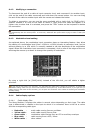
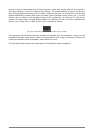
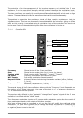
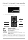
7.1.2.1 Controller 921A
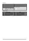
Oscillator 921A
Frequency General tuning of the 3 slave oscillators
State General tuning mode choice (by 1/2 tone, by octave)
Impulse width Signal impulse width “Sawtooth”, “Square”, “Triangle”
FM Inputs Frequency modulation input connection jacks
WPM Inputs Pulse width modulation connection jacks
Keyboard follow Keyboard follows choice tuning the master oscillator (off, no, follow 1,
2, 3 or 4).
Sequencer Choice Choice of the sequencer output tuning the master oscillator (no
sequencer, sequencer 1, 2, 3 or 4).
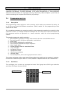
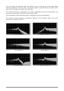
The general tuning of the 3 slave oscillators is done with the “Frequency” knob. Depending on
the position of the “State” interrupter, the range of the knob is +/- an octave by semitone or
+/- six octaves par fifth and quarter.
The impulse width affected to the “sawtooth”, “triangle” and “square” signals of the 3 slave
oscillators is modified with the “Width” knob.
Three frequency modulation inputs and 2 impulse width modulation inputs allow the control of
these parameters thanks to the outputs of the other modules.
When one of these inputs is connected, a click on the Jack will modify the amplitude of the
modulation. The Jack knob functions like a rotating dial where the position for inactivity (no
modulation) is at the center. The modulation can thus be positive (button turned to the right)
or negative (button turned to the left).
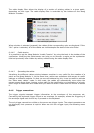
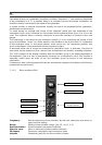
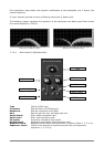
Frequency
State
Impulse width
PWM Inputs FM Inputs
Sequencer choice
Keyboard follow