


Pedal Settings (Control/Expression)
37
Quick Guide Overview Outputting Sound Eects Saving Pedal Settings System MIDI/USB Appendix
Setting Each Pedal Functions to
Individual Patches (Assign)
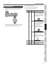
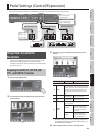
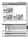
You can set the [PHRASE LOOP] Pedal, [ACCEL/CTL], [EXP] pedal,
EXP PEDAL SW and external pedals (footswitch and expression
pedal) connected to the rear panel’s SUB CTL 1, 2/SUB EXP jacks for
each individual patch. You can save up to eight separate settings
per patch (using Assign numbers 1 through 8) that determine what
parameters are controlled by which pedals.
* If you want to use the [PHRASE LOOP] pedal with the
assignment you specify, you must turn “PHRASE LOOP PEDAL
FUNC” (p. 40) o. For other pedals, you must set “PREFERENCE”
(p. 41) to “PATCH.”
* You can specify the individual parameter that will be controlled
by each pedal.
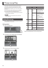
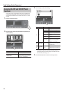
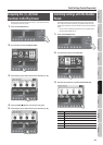
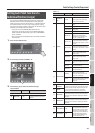
1. Press the [CTL/EXP] button.
2. Turn knob [4] to select “ASSIGN 1–8.”
3. Use knobs [5]–[8] to select the desired settings.
ASSIGN COMMON
Parameter Value Explanation
Page 1
[8] INPUT SENS 0–100
This adjusts the input sensitivity
when INPUT LEVEL is selected for
SOURCE.
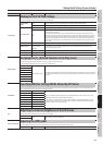
ASSIGN 1–8
Parameter Value Explanation
Page 1
[5]
ASSIGN ON/
OFF
OFF, ON
Turns the ASSIGN 1–8 on/o.
* This setting is not saved along
with the quick settings.
[6] SOURCE
EXP PEDAL
Assigns the GT-100’s built-in [EXP]
pedal.
EXP PDL SW Assigns the EXP pedal switch.
P.LOOP PEDAL
Assigns the GT-100’s [PHRASE
LOOP] pedal.
ACC/CTL PDL Assigns the [ACCEL/CTL] pedal.
SUB EXP PDL
Assigns the external expression
pedal (such as the separately
available EV-5) connected to the
SUB CTL 1, 2/SUB EXP jack.
SUB CTL1 PDL
Assigns the external footswitch
(FS-5U, FS-6; available separately)
connected to the SUB CTL 1, 2/SUB
EXP jack.
SUB CTL2 PDL
Assigns the external foot switch
(FS-5U, FS-6; available separately)
connected to the SUB CTL 1, 2/SUB
EXP jack.
INT PEDAL
Refer to “Virtual expression pedal
system (Internal Pedal / Wave
Pedal)” (p. 39))
WAVE PEDAL
Refer to “Virtual expression pedal
system (Internal Pedal / Wave
Pedal)” (p. 39)
INPUT LEVEL
The assigned target parameter
will change according to the input
level.
CC#1–#31
Control Change messages from an
external MIDI device.
CC#64–#95
Control Change messages from an
external MIDI device.
[7] SOURCE MODE
MOMENT
The normal state is O (minimum
value), with the switch On
(maximum value) only while the
footswitch is depressed.
TOGGLE
The setting is toggled On
(maximum value) or O (minimum
value) with each press of the
footswitch.
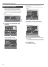
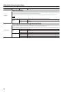
Page 2
[5]
TARGET
CATEGORY
This selects the parameter to be changed.
For details on all parameters, download the “GT-100
Parameter Guide” (PDF le) located under “GT-100”
in the list of “Owner’s Manuals” on the Roland
website (http://www.roland.com/support/en/).
[6] TARGET
[7] TARGET MIN
This sets the minimum value for the range in
which the parameter can change. The value diers
depending on the parameter assigned for TARGET
parameter.
[8] TARGET MAX
This sets the maximum value for the range in
which the parameter can change. The value diers
depending on the parameter assigned for TARGET
parameter.
Page 3
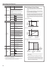
[5] ACT RANGE LO 0–126
You can set the controllable range
for target parameters within the
source’s operational range. Target
parameters are controlled within
the range set with ACT RANGE LO
and ACT RANGE HI. You should
normally set ACT RANGE LO to 0
and ACT RANGE HI to 127.
[6] ACT RANGE HI 1–127