


Section 4 – Connections
4-2 – 1.00 – 06/97
how to use the DA-98 with timecode, see 10,
“Operations related to timecode”.
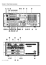
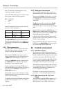
The two XLR timecode connectors [37] carry bal-
anced signals with the following polarity:
However, unbalanced signals may be used, with
only pins 1 and 2 connected.
The
TIMECODE OUT
connector either transmits
internally-generated timecode or re-shaped or re-
generated timecode echoed from the
TIMECODE
IN
connector.
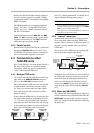
4.2.2 Video connections
This pair of BNC connectors [38] is used to pro-
vide video frame reference clocking when the
DA-98 is used with video equipment.
The front panel
CLOCK
switch [30] is used to
change between clock sources, and should be set
to
VIDEO
when synchronizing to video sync.
Connect the
VIDEO IN
connector of the DA-98 to
the VIDEO OUT of a video unit. This signal
should be a 1 Vp-p composite signal.
If other equipment (such as other DTRS units)
also need the video frame reference clock, the sig-
nal received at the
VIDEO IN
is echoed at the
VIDEO THRU
connector.
If the DA-98 is the last unit in the chain of video
equipment, there is no need to terminate it, as this
circuit is self-terminating.
For details of how the DA-98 can be synchronized
to video frame information, see 11.1.1, “Video
clocking”.
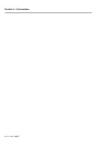
4.2.3 Word clock connections
This set of BNC connectors [39] is used to syn-
chronize the DA-98 to other digital audio devices.
The front panel
CLOCK
switch (page 2-3) is used
to change between clock sources, and should be
set to
WORD
when synchronizing to an external
word clock.
The
IN
jack should be connected to the WORD
SYNC OUT of the digital audio device from
which the DA-98 is to receive the synchronization
clock.
Note the difference between the
OUT
and the
THRU
connectors.
OUT
is used to carry word clock
signals generated by the DA-98, and
THRU
is used
to echo the signals received at
IN
.
If the DA-98 is the last unit in the chain of video
equipment, there is no need to terminate it, as this
circuit is self-terminating.
Also note that if the DA-98 is connected to other
DTRS units, the
WORD SYNC
jacks do not need to
be connected between the DTRS units.
4.3 Control connections
4.3.1 RS-422 connector
This connector is used to connect the DA-98 to
other controllers or editors which will control the
DA-98 using the Sony P2 protocol, or a bus proto-
col, such as that used by the TASCAM ES-61.
If you are in doubt about the compatibility of such
a device, please consult TASCAM or your TAS-
CAM dealer, who will be able to advise you.
The DA-98 can emulate (through software control
accessed through menu 6) a number of devices for
compatibility with almost any controller. See
11.1.2, “Emulation” for details.
Full details of control using this connector are
given in 11.1, “Use with 9-pin external control”.
4.3.2 MIDI connectors (IN , OUT and
THRU)
These standard 5-pin DIN MIDI connectors [41]
are used to carry MIDI Time Code (MTC) and
MIDI Machine Control (MMC) information
Pin # Connection
1 Ground
2Hot
3Cold
IN (balanced) OUT (balanced)
Level 0.5 Vp-p to
10.0Vp-p
2Vp-p
Impedance > 10k
Ω
< 100
Ω