


Section 4 – Connections
06/97 – 1.00 – 4-3
between the DA-98 and other suitably-equipped
units (for instance, sequencers capable of being
synchronized to MTC, and capable of transmitting
MMC commands).
The MIDI functions are accessed through menu
group 7. See 10.4.5, “Using MIDI Time Code
(MTC)” and 11.3.1, “MMC commands and the
DA-98” for full details.
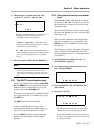
Note the difference between
MIDI OUT
and
MIDI
THRU
. The
OUT
connector outputs signals which
originate from the DA-98. The
THRU
connector
echoes messages received at the
IN
.
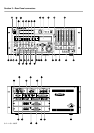
4.3.3 Parallel control
Parallel control by and of the DA-98 is performed
through the
CONTROL I/O
port [42]. See 15.1.6,
“CONTROL I/O connector pinout” for details of
how to connect other equipment to this port.
4.4 Connection to other
TASCAM units
By a “TASCAM unit”, we mean another DA-98, a
DA-88 or a DA-38 unit, or an optional remote
control unit, which may also be connected in a
“chain” with multiple DTRS units.
4.4.1 Multiple DTRS units
Use a TASCAM PW-88S cable when connecting
other units to the
REMOTE/SYNC IN
connector
[43] or to the
SYNC OUT
connector ([44]).
This synchronization cable will carry the internal
synchronization code and the transport signals,
etc. There is no need to make any other connec-
tions, apart from the audio connections (either
digital or analog).
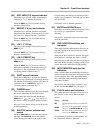
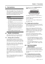
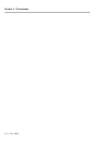
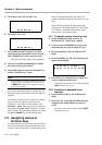
If more than one DTRS unit is to be used, the first
unit in the chain must have its Machine ID set to
“1”, (“0” in the case of DA-88s) and subsequent
units must have their IDs set in order with no gaps
in the numbering sequence. Note that the diagram
below does not show any audio connections.
`o`t`r`g `o`t`r`g`o`t`r`g
Machine ID 1
(master)
Machine ID 2
(slave 1)
Machine ID 3
(slave 2)
Termination
plug
PW-88S PW-88S
See 9.2.2, “Setting machine ID” for details of set-
ting the Machine ID using menu group 3.
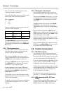
4.4.2 “Indirect” word sync
As mentioned earlier, there is usually no need to
use a word clock when connecting DTRS units
together. There is, however, an occasion when it is
necessary to carry external word sync between
DTRS units.
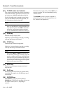
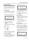
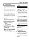
This is when a slave DTRS unit is recording digi-
tally from another digital audio device:
Though the slave will receive its word clock from
the master unit, the master itself must receive its
word clock from the other digital audio device.
In this case, the master unit will have its clock
source set to
WORD
, and the slave will receive its
clock from the master unit through the
SYNC IN
[43].
4.4.3 Meter unit (MU-8824)
The optional MU-8824 external meter bridge unit
can be connected using a PW-88M cable from the
METER UNIT
connector [46]. You do not need to
make any settings on the DA-98 when connecting
the meter unit.
WARNINGS
The last unit in the chain must be terminated (a TAS-
CAM termination plug must be plugged into the
SYNC
OUT
of the last machine in the chain.
Once again, only use TASCAM cables for connection of
equipment to and from the DA-98.
`o`t`r`g`o`t`r`g
Machine ID 1
(master, but
CLOCK set to
WORD)
Machine ID 2
(slave 1)
Termination
plug
PW-88S
IF-88SD
TDIF-1 digital
audio
Digital SDIF-2
device
SDIF-2
digital audio
Word clock signal