


– 16 –
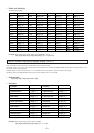
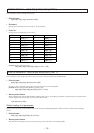
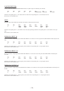
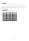
CLIP/PROTECTION
Turning on/off of the CLIP and PROTECTION indicators of speaker output is indicated by the 8-bit data.
bit7 bit6 bit5 bit4 bit3 bit2 bit1 bit0
0 1 0 0 0 PROTECTION CH2 CLIP CH1 CLIP
When the corresponding bit is ‘1’, the indicator turns on. When the corresponding bit is ‘0’, the indicator turns off.
Bit-2 to bit-7 are fixed all the time.
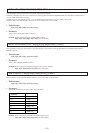
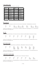
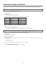
GATE
Operating status of the GATE of the automatic mixer block is indicated by the 8-bit data.
bit7 bit6 bit5 bit4 bit3 bit2 bit1 bit0
0 1 MIC6/ MIC5/ MIC4 MIC3 MIC2/ MIC1/
LINE2 LINE1
WL2 WL1
When the corresponding bit is ‘1’, the GATE is in the close state (operating). When the corresponding bit is ‘0’, the GATE is in the open
state.
Bit-6 and bit-7 are fixed all the time.
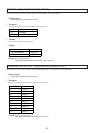
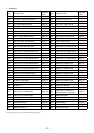
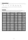
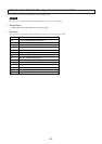
PARALLEL INPUT1-6
Presence or absence of input signal to the PARALLEL INPUT1 to 6 connectors on the rear panel of the SRP-X700P is indicated by the 8-bit
data.
bit7 bit6 bit5 bit4 bit3 bit2 bit1 bit0
0 1 IN6 IN5 IN4 IN3 IN2 IN1
When the corresponding bit is ‘1’, input signal is present. When the corresponding bit is ‘0’, input signal is absent.
Bit-6 and bit-7 are fixed all the time.
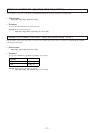
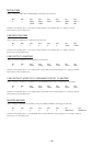
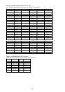
PARALLEL INPUT7-12
Presence or absence of input signal to the PARALLEL INPUT7 to 12 connectors on the rear panel of the SRP-X700P is indicated by the
8-bit data.
bit7 bit6 bit5 bit4 bit3 bit2 bit1 bit0
0 1 IN12 IN11 IN10 IN9 IN8 IN7
When the corresponding bit is ‘1’, input signal is present. When the corresponding bit is ‘0’, input signal is absent.
Bit-6 and bit-7 are fixed all the time.
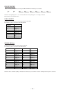
PARALLEL OUTPUT1-6
Presence or absence of output signal at the PARALLEL OUTPUT1 to 6 connectors on the rear panel of the SRP-X700P is indicated by the 8-
bit data.
bit7 bit6 bit5 bit4 bit3 bit2 bit1 bit0
0 1 OUT6 OUT5 OUT4 OUT3 OUT2 OUT1
When the corresponding bit is ‘1’, output signal is present. When the corresponding bit is ‘0’, output signal is absent.
Bit-6 and bit-7 are fixed all the time.