


– 61 –
SPEAKER OUTPUT : 43[H] 4F[H] 53[H] 50[H] (‘COSP’)
This command is used to set the SPEAKER OUTPUT.
Various setups can be memorized in the scene memories by specifying these scene Nos.
• Packet format
43[H] 4F[H] 4C[H] 33[H] “parameter” 0D[H]
• Parameter
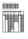
The parameter consists of the 22 bytes all the time in the order as shown in the table below.
When you specify NONE (30[H] ‘0’) as the scene No. in the 1st byte, you can establish the present setup.
At the same time, when you specify the scene No. (31[H] (‘1’) through 44[H] (‘D’)), parameters of the subsequent 2nd through 22nd
byte are written in the scene memory.
Method of setting the scene No. and setting index of each channel, refer to the GROUP FADER command (pages 29 and 30).
For the packet example, see the example of the LINE 3 INPUT command on page 35. However, the parameter length becomes 22 bytes.
• Function ON/OFF (2nd byte)
This command is used to set the mode of the SPEAKER OUT terminal.
When you want to set the Lo Imp. mode, set 40[H] (‘@’). When you want to set the 70V LINE mode, set 41[H] (‘A’).
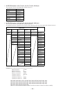
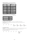
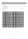
• CH1, 2 selector (11, 21st byte)
This command is used to select the signal to be output from the SPEAKER OUTPUT terminal.
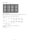
CHANNEL CHANNEL
LINE OUTPUT 1 30[H] (‘0
’
) LINE OUTPUT 6 35[H] (‘5
’
)
LINE OUTPUT 2 31[H] (‘1
’
) LINE OUTPUT 7 36[H] (‘6
’
)
LINE OUTPUT 3 32[H] (‘2
’
) LINE OUTPUT 8 37[H] (‘7
’
)
LINE OUTPUT 4 33[H] (‘3
’
) REC OUT1 38[H] (‘8
’
)
LINE OUTPUT 5 34[H] (‘4
’
) REC OUT2 39[H] (‘9
’
)
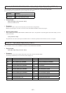
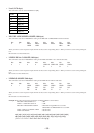
byte Parameter name
1st SCENE No.
2nd FUNCTION ON/OFF
3rd-10th CH1 INDEX
11th CH1 SELECTOR
12th CH1 ATT
13th-20th CH2 INDEX
21st CH2 SELECTOR
22nd CH2 ATT