


– 54 –
ROUTING : 43[H] 52[H] 4C[H] 31[H]-38[H] (‘CRL1-8’)
43[H] 52[H] 52[H] 31[H]-32[H] (‘CRR1-2’)
This command is used to set the routing for the OUTPUT channels.
Various setups can be memorized in the scene memories by specifying these scene Nos.
The commands that correspond to the respective channels are shown below.
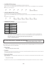
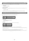
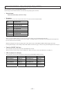
• Packet format
43[H] 52[H] 4C[H] 31[H] “parameter” 0D[H]
(In the case of LINE OUTPUT1)
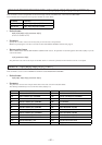
• Parameter
The parameter consists of the 20 bytes all the time in the order as shown in the table below.
When you specify NONE (30[H] ‘0’) as the scene No. in the 1st byte, you can establish the present setup.
At the same time, when you specify the scene No.(31[H] (‘1’) through 44[H] (‘D’)), parameters of the subsequent 2nd through 20th byte
are written in the scene memory.
For the method of setting the scene No., see the GROUP FADER command (pages 29 and 30).
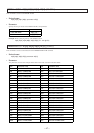
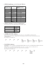
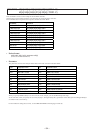
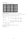
CHANNEL Command
LINE OUTPUT 1 43[H] 52[H] 4C[H] 31[H] ‘CRL1’
LINE OUTPUT 2 43[H] 52[H] 4C[H] 32[H] ‘CRL2’
LINE OUTPUT 3 43[H] 52[H] 4C[H] 33[H] ‘CRL3’
LINE OUTPUT 4 43[H] 52[H] 4C[H] 34[H] ‘CRL4’
LINE OUTPUT 5 43[H] 52[H] 4C[H] 35[H] ‘CRL5’
LINE OUTPUT 6 43[H] 52[H] 4C[H] 36[H] ‘CRL6’
LINE OUTPUT 7 43[H] 52[H] 4C[H] 37[H] ‘CRL7’
LINE OUTPUT 8 43[H] 52[H] 4C[H] 38[H] ‘CRL8’
REC OUT 1 43[H] 52[H] 52[H] 31[H] ‘CRR1’
REC OUT 2 43[H] 52[H] 52[H] 32[H] ‘CRR2’
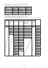
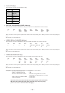
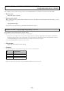
byte Parameter name byte Parameter name
1st SCENE No. 11th LINE4 A-C,F R LEVEL
2nd MIC1/WL1 LEVEL 12th LINE4 D-E L LEVEL
3rd MIC2/WL2 LEVEL 13th LINE4 D-E R LEVEL
4th MIC3 LEVEL 14 th LINE4 D-E LS LEVEL
5th MIC4 LEVEL 15 th LINE4 D-E RS LEVEL
6th MIC5/LINE1 LEVEL 16th LINE4 D-E C LEVEL
7th MIC6/LINE2 LEVEL 17th LINE4 D-E SW LEVEL
8th LINE3 L LEVEL 18th MIC1/WL1-MIC6/LINE2 ON/OFF
9th LINE3 R LEVEL 19th LINE3-LINE4A-C ON/OFF
10th LINE4 A-C,F L LEVEL 20th LINE4 D,E ON/OFF