


– 42 –
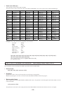
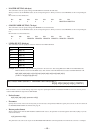
• Packet format
43[H] 49[H] 4D[H] 31[H] “parameter” 0D[H]
(In the case of MIC1/WL1 input channels)
• Parameter
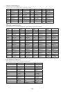
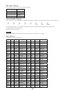
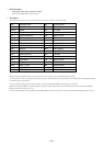
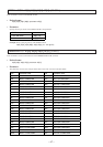
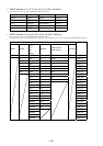
The parameter consists of the 41 bytes all the time in the order as shown in the table below.
When you specify NONE (30[H] ‘0’) as the scene No. in the 1st byte, you can establish the present setup.
At the same time, when you specify the scene No.(31[H] (‘1’) through 44[H] (‘D’)), parameters of the subsequent 2nd through 41th bytes
are written in the scene memory.
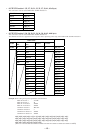
For the method of setting the scene No. and index, refer to the GROUP FADER command (pages 29 and 30).
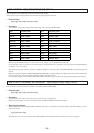
Method of setting the PEQ1-3 frequency, PEQ1-3 Q, PEQ1-3 Gain, Gain Limit level and fader level is the same as that of the LINE 3
INPUT command. See pages 32 to 35.
For the packet example, see the example of the LINE 3 INPUT command on page 35. However, the parameter length becomes 41 byts.
byte Parameter name byte Parameter name
1st SCENE No. 25th 46[H] (‘F’) fixed
2nd-9th INDEX 26th FR1 GAIN
10th TRIM 27th FR2 Frequency
11th FUNCTIONON/OFF 28th 46[H] (‘F’) fixed
12th PEQ1 Frequency 29th FR2 GAIN
13th PEQ1 Q 30th FR3 Frequency
14th PEQ1 GAIN 31st 46[H] (‘F’) fixed
15th PEQ2 Frequency 32nd FR3 GAIN
16th PEQ2 Q 33rd FR4 Frequency
17th PEQ2 GAIN 34th 46[H] (‘F‘) fixed
18th PEQ3 Frequency 35th FR4 GAIN
19th PEQ3 Q 36th FR5 Frequency
20th PEQ3 GAIN 37th 46[H] (‘F’) fixed
21st 26[H] (‘&’) fixed 38th FR5 GAIN
22nd 2F[H] (‘/’) fixed 39th COMPRESSOR
23rd 30[H] (‘0’) fixed 40th GAIN LIMIT LEVEL
24th FR1 Frequency 41st FADER LEVEL