


6 Agilent E1538A Enhanced Frequency/Totalize/PWM SCP
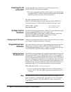
Setting Configuration Switches
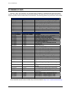
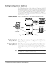
The SCP has three packages of eight switches each. The package labeled OE
(Output Enable) determines a channel’s I/O direction. The package labeled
PU (pull-up) controls whether or not a channel is floating or pulled up to an
internal 5V supply. The package labeled VRS (for channels 0 and 1 only)
can enable special input signal conditioning compatible with variable
reluctance sensors. For a discussion on using the VRS mode, see "VRS Mode
Input Operation" on page 10.
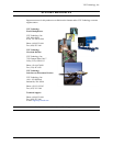
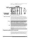
Locating switches Figure 2 shows the location of each channel’s configuration switches.
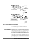
Configuring Input-
Output direction
Refer to Figure 2 for the location of the eight Output Enable (OE) switches.
Move the channel’s switch handle to the ON position for output, and to the
OFF position for input.
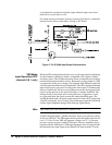
Configuring Channel
Pull-up Resistor
Refer to Figure 2 for the location of the eight Pull-up Enable (PU) switches.
Move the switch handle to the ON position to connect the pull-up resistor
(connected from channel terminal to an internal +5V), and to the OFF
position to disconnect the pull-up resistor (high impedance input/open drain
output).
Note Pull-Up enable ON is not allowed for channels that have their VRS enable
ON (VRS is only available on channels 0 and 1).
Figure 2. Switch Location and Example Settings